00198502-02_VD_SIPLACE_Pro_15.1_R18-1_DE_EN.pdf - 第19页
SIPLACE Pro 15.1 (R 18 - 1) / V ersion Description 05/2018 Edition 19 5.4 Line Configura tion with Inspecti on Systems and AOI Devices Inspection Sy stems ha ve been added to t he Devices of Line Tree Vie w in the Line E…
SIPLACE Pro 15.1 (R18-1) / Version Description 05/2018 Edition
18
5.3 "The Hermes Standard" – New Communication Protocol
"The Hermes Standard" is a new communication protocol for SMT assembly lines that can be used
alternatively to the electrical SIPLACE SMEMA interface. With this protocol, more information can
be transferred with the board down the line like unique board Ids, barcodes, conveyor speed, board
length / width / thickness. All this information can be transferred down the complete line, without
any interruption. Up to now, this was only possible within a SIPLACE SMEMA cluster. If all devices
in the line support "The Hermes Standard", whispering down the line is possible within "The
Hermes Standard" cluster as it is within the SIPLACE SMEMA cluster.
"The Hermes Standard" can be used on all placement machines supported by station software
version ≥ 711. Please refer to the station software Version Description, item no. [00198500-xx].
It is also supported that the line is divided for example into two "The Hermes Standard" clusters, if
other devices in the line do not support "The Hermes Standard".
A button has been added to the Line Editor in SIPLACE Pro Desk, to all production line editors
(e.g. Setup Editor, Recipe Editor, Job Editor) and to the graphical line view in the Line Control GUI
with which the user can hide or show generic devices in the graphical line view.
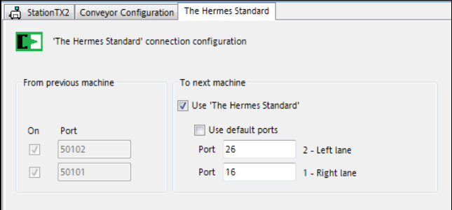
"The Hermes Standard" connection configuration has been added to the Line Editor in which the
devices are configured (printers, generic devices, process lens devices and placement stations).
Figure 5-1: "The Hermes Standard" connection configuration
The user can only configure "The Hermes Standard" device connections to the next device. The
configuration of the connection to the previous device is displayed read-only, as this configuration
is edited in the respective editor of the previous device.
The Use 'The Hermes Standard' check box specifies whether the connection shall use "The
Hermes Standard" protocol. If not enabled, the SIPLACE SMEMA protocol will be used.
In the Line Control GUI, the new line view 'The Hermes Standard' connection View can be
selected. In this view, the user can check and download "The Hermes Standard" device connection
configuration. Additionally, a report can be created and printed.
Restrictions
– No support for stations with shuttle.
– No support for devices with IPv6 addresses.
SIPLACE Pro 15.1 (R18-1) / Version Description 05/2018 Edition
19
5.4 Line Configuration with Inspection Systems and AOI Devices
Inspection Systems have been added to the Devices of Line Tree View in the Line Editor. Here
the user can create solder paste inspection devices. Currently, only ASM Process Lens is
supported. IP address, host name and software version can be edited.
The Custom generic line device has been extended by two new attributes: Manufacturer (name of
the manufacturer of the device) and Equipment ID (Id of the machine / serial number).
The existing generic line device type, containing Undefined and AOI has been extended by the
following new types:
AOXI, AXI, ClassificationArea, RepairArea, PlacementMachine, Printer, SPI, Oven.
5.5 New Placement Force – Very Low Force in Placement, Pickup and
Dipping Processes
The new very low force state has been added to SIPLACE Pro.
In the Handling tab of the Component Shape Editor, the force state for placement, pick-up and
dipping can be set in a drop-down menu:
– Standard: the standard force is used.
– Manual: the user can enter own values.
– Very low: the very low force state is enabled.
The very low force state can only be used for the following placement heads:
C&P20 M2, C&P20 P and (from R18-1) C&P20 P2.
5.6 SEMO CRF80 – New Tape Feeder
The new SEMO CRF80 tape feeder from the SEMO company is supported by SIPLACE Pro and
occupies seven tracks on the X-table. The feeder is distributed directly by the manufacturer.
5.7 External Barcode Reader in the Middle of the Line
External barcode readers can now be used in front of any placement machine in the line together
with the Board Gate Keeper. The Board Gate Keeper can be defined as preceding whisperer of
any station, e.g. the third station in the line.
Example:
The line consists of three placement machines. In front of the line and between the second and
third station there is a conveyor with an integrated board barcode reader. These readers shall
be used for traceability purposes and be connected with Traceability via the Board Gate
Keeper.
If the Board Gate Keeper shall be configured as preceding whisperer for both the first and the third
station, the Use station Setting has to be set in the Setup Editor for the line.
SIPLACE Pro 15.1 (R18-1) / Version Description 05/2018 Edition
20
Additionally, the External Board Barcode option has to be set in the respective station setup of
the first and the third station to define that the board barcodes shall be whispered from external (=
from the Board Gate Keeper on the line computer). Only external inkspots, panel fiducials and
(external) virtual inkspots can be whispered from the Board Gate Keeper to the first and the third
station.
The station software only supports one preceding whisperer. The Board Gate Keeper is then the
only preceding whisperer of the e.g. third station. Therefore, the (internal) inkspots and panel
fiducials, read by the first station, cannot be whispered e.g. from the second to the third station (via
the barcode transferred from the Board Gate Keeper to the third station).The third station has to re-
read all (internal) inkspots and panel fiducials again.
5.8 Barcode Conditions for Traceability Purposes
When reading the barcode with the board camera for traceability purposes, the Vision system shall
verify that the recognized barcode is the correct one to be used for traceability.
To avoid that an incorrect barcode is read, the user can define conditions for the barcode in the
Vision system at the station. If a barcode does not fulfill all conditions, the Vision system looks for
another barcode with valid conditions in the region of interest. The conditions are saved in the
Barcode Fiducial in SIPLACE Pro.
SIPLACE Pro Line Control sends the data to stations running station software version ≥ 711.The
data can be taught at the station and saved back into SIPLACE Pro. The barcode data cannot be
edited in SIPLACE Pro but deleted in the Fiducial Editor by pressing the Remove all vision data
button.
5.9 BOM-Merger: Automatic Component Shape Linking
The BOM Merger can create components in SIPLACE Pro although they are not yet available in
the database. The BOM Merger has been extended to automatically assign the component shape
of the component at existing component placements to the newly created component in the BOM
file.
The BOM Merger links newly created components to the already existing component shape which
is referenced by the current component of the original component placement. Components that
already exist and for which there is no reference to a component shape will also be automatically
linked to the component shape of the original component in the placement list. Conversely, existing
components which do reference a component shape will be unchanged.
Existing alternative component shapes assigned to the original component will also be transferred
to the target component. No other attributes of the original component will be transferred.