wire-bonder.pdf - 第33页
WEST•BOND MODEL 454647E SER IES INSTRUCTION MANUAL 27 OPERATION Align Menu 2 This menu is used for scanning the other bonds or changing the Y Offsets. The purpose i s to verify all the bond positions to deci de whether t…
WEST•BOND MODEL 454647E SERIES INSTRUCTION MANUAL
26
OPERATION
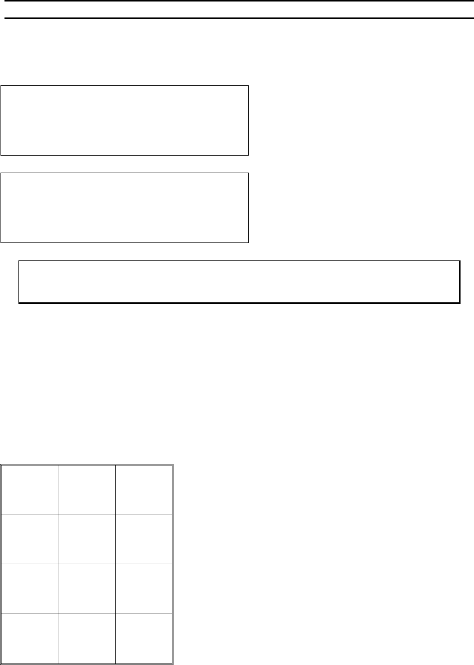
Information
To see this menu, press and hold key 5 in the More Options Menu.
Model 454647E,“Version 5.50” -->4500
West Bond Inc.
IN MOST MENUS
1=Escape 2=Go To 3=Home
Go to previous menu upon release of key 5. This
screen is also seen briefly during power-up.
Model 454647E,“Version 5.50”-Aug 10,2000
West Bond Inc.
IN MOST MENUS
1=Escape 2=Go To 3=Home
If key 5 is held for 5 seconds the Software date will
replace the model number in the upper right corner
ϑ To call “Info”
From the M
ORE OPTIONS menu press and hold key 5
Key Format:
Escape
1
Go To
Device/Type
2
Home
3
4
5
6
7
8
9
A
0
G
WEST•BOND MODEL 454647E SERIES INSTRUCTION MANUAL
27
OPERATION
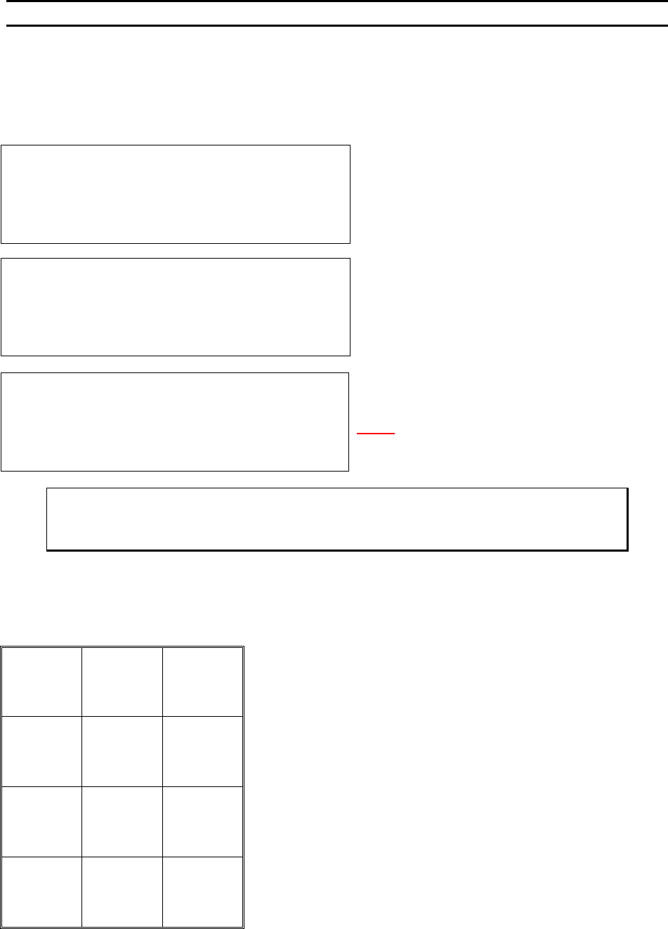
Align Menu 2
This menu is used for scanning the other bonds or changing the Y Offsets. The purpose is to verify all the
bond positions to decide whether the station needs to be rotated or not; since bonding motion is straight-
front-to-back.
SCAN BOND 2 of 2: 120 from Bond 1
5=Increase (0.02500”)
7=Prev bond 8=Y restore 9=Next bond
A=Prev menu 0=Decrease G=OK
The X-Y Manipulator is Locked. Use 5 or 0 to adjus
t
the Bond position.
N
OTE! 120 is an example of Y offset position, thi
s
number will be updated to a permanent number when
the G key is pressed if the new number is different.
ϑ To call “Align Menu 2”
From the H
OME menu press 8 (MORE OPTIONS) and then press 9 (SCAN BONDS)
Key Format:
1
2
Home
3
4
Increase
5
6
Previous
bond
7
Restore
8
Next bond
9
Previous
menu
A
Decrease
0
OK
G
SCAN BOND
Device 1, Type 1: (2 Bonds)
-->USE MANIPULATOR TO ALIGN TV CROSSHAIR
TO BOND 1 AND PRESS 9 WHEN READY
Y OFFSET of Bond #1: Always 0
7=Move XY 9=Next bond
A=Prev menu
Bond 1 is not moveable. Use key 7 to realign the TV
crosshairs to bond 1 if not centered on Bond 1.
WEST•BOND MODEL 454647E SERIES INSTRUCTION MANUAL
28
OPERATION
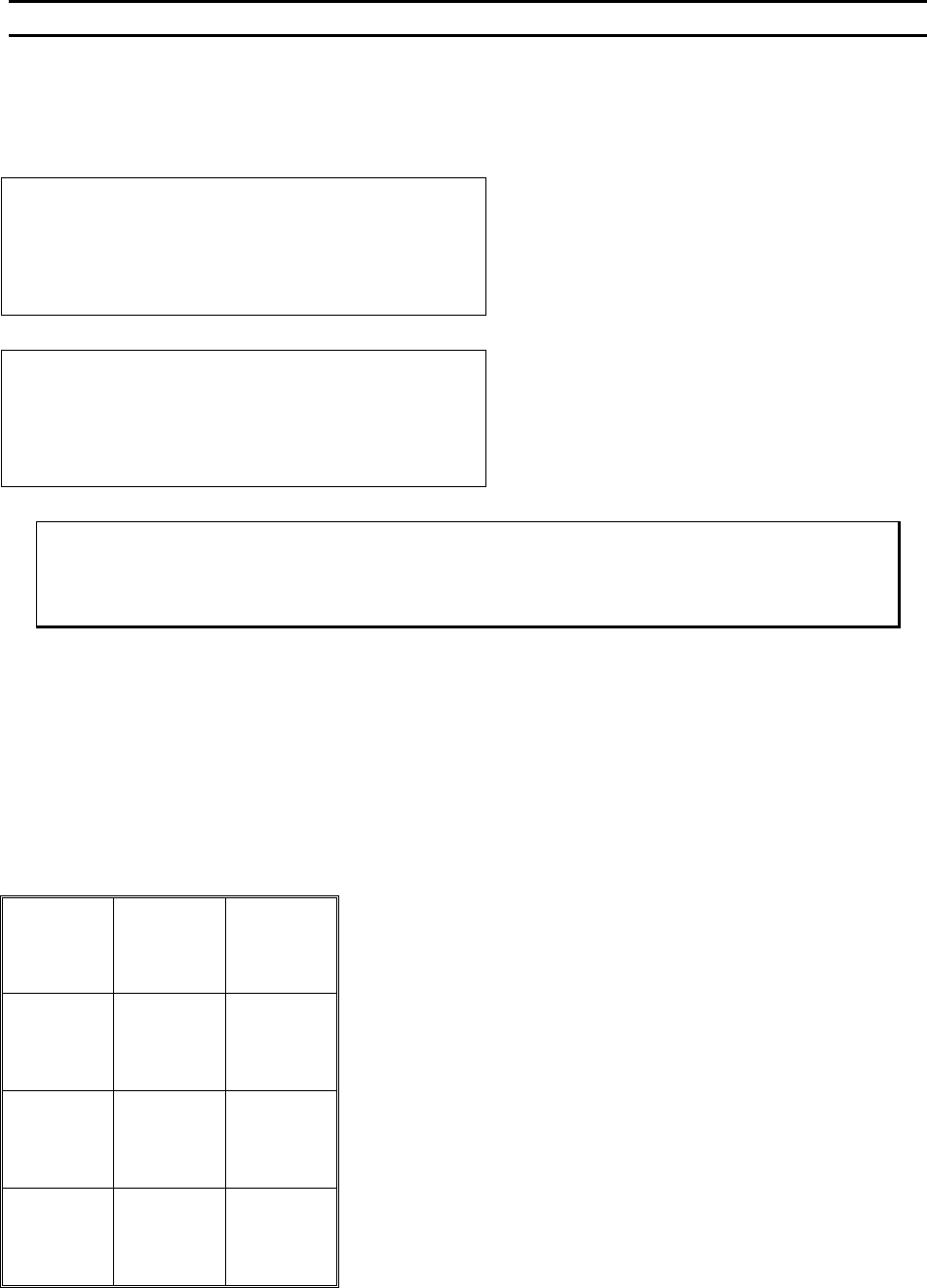
Work Height Elevation
Before any new part is to be programmed, or run for the first time, the work elevation needs to be verified.
This is so that the search elevations and the looping heights will be correct, and no damage to the tool will
occur.
Restart Height Elevation: 1400 from top
Suggested setting is 800 for 4700E Mode.
4=Key in 5=Up (0.29167”)
7=Work Height 8=Suggest
A=Prev Option 0=Down G=Next Option
== WORK HEIGHT VERIFICATION ==
(Look in microscope)
Tool will run down during this mode.
Select the median bond height & Press G
Select a bond area that will be in the
middle of the bond range and press G.
Adjust the Table according to the LCD.
ϑ To call “Work Verification Menu”
At the H
OME menu press 4 (EDIT), 6 (MACHINE), 9 (RESTART HEIGHT), and then 7 (WORK
HEIGHT VERIFICATION)
Key Format:
Previous
menu
1
Go To
Device/Type
2
Home
3
Key In
4
↑ Y up
5
6
Work
Height
7
Suggest
8
9
Previous
Option
A
↓ Y down
0
Next
Option
G