wire-bonder.pdf - 第8页
WEST•BOND MODEL 454647E SER IES INSTRUCTION MANUAL 2 PRODUCT OVERVIEW Application Machines of this seri es bond aluminum or gold wi res from 0.0007 in. to 0.002 in. diam eter, primarily to stitch bond a succe ssion of pa…
WEST•BOND MODEL 454647E SERIES INSTRUCTION MANUAL
1
INTRODUCTION
WEST•BOND’S new “E” Version starts the twentieth year of the Model 4500 tradition. This machine was
revolutionary at its inception as the first to make a wire bond connection fully under programmable
software control executed digitally by motors, thus making possible the manufacture of high frequency,
high power semiconductor devices where connections must be identical. The original design, with digi-
switches for input and with LED’s to display individual data lines by binary value, remained unchanged by
customer insistence until finally supplanted by the current 4500 Model of the “B” Series. Now, Model
454647E brings forward the new advances of the “E” Series, notably the placement of all machine
mechanism above the work plane to allow unlimited access, and the setting of axis brakes to lock on
target. In this model the tool, rather than the work, is moved, both for alignment and for bonding, with the
work pre-rotated. There is choice of alignment by either microscope or video. Bond heads are built
around a 63 kHz ultrasonic transducer and provide full three-way convertibility.
When operating in the 4500E mode, the 454647E is an ultrasonic wedge-wedge wire bonder designed to
interconnect wire leads to semi-conductor, hybrid, or microwave devices. The machine bonds aluminum
or gold wires ranging from 0.0007 in. to 0.002 in. Bonds are by the wedge-wedge technique using
ultrasonic energy to attach aluminum wire at room temperature and adding work piece heat for gold wire.
Wire is clamped and threaded diagonally under the bonding wedge, allowing independent feeding action
but requiring front-to-back bonding direction.
When operating in the 4600E mode, the 454647E is a thermosonic wedge-wedge wire bonder designed
to interconnect wire leads to semiconductor, hybrid, or microwave devices. The machine bonds aluminum
or gold wires ranging from 0.0007 in. to 0.002 in. and aluminum or gold ribbon ranging from 0.0005 in. x
0.002 in. to 0.001 in. x 0.01 in. Bonds are made by the wedge-wedge technique using ultrasonic energy
and work piece heat. Wire is clamped and threaded vertically through a hollow wedge, allowing
independent feeding action but requiring front-to-back bonding direction.
When operating in the 4700E mode, the 454647E is a thermosonic ball-wedge wire bonder designed to
interconnect wire leads to semiconductor, hybrid, or microwave devices. The machine bonds gold wires
ranging from 0.0007 in. to 0.002 in. Bonds are made by the ball-to-wedge technique using ultrasonic
energy and work piece heat. Wire is clamped and threaded vertically through a hollow capillary, allowing
independent feeding action. The connection is begun with a ball formed on the end of the wire stock by
electric discharge, and completed by a wedge bond under the end of the capillary tool. The bonding tool
is guided manually by the operator using hand/eye reference to bond targets and elevations.

WEST•BOND MODEL 454647E SERIES INSTRUCTION MANUAL
2
PRODUCT OVERVIEW
Application
Machines of this series bond aluminum or gold wires from 0.0007 in. to 0.002 in. diameter, primarily to
stitch bond a succession of parallel multi-arch wires, but useful for bonding any program of shaped
connections. Three bond methods are available by tool head conversion; angled-feed wedge bonding,
vertical-feed wedge bonding, and ball bonding. Both wedge bond methods require front-to-back wire
progress, hence pre-rotation of the work piece. Wherever possible, angled feed wedge bonding is
recommended because clamps very near the bond foot can have the best effect to work the wire into
arches. Ball bond connections can be similarly shaped, even by complex motions, if rotation is pre-set.
This machine is also uniquely capable of making a succession of spaced single-ball bonds. Further, a
machine of this series can be assembled without feed mechanism to Tab Bond a pattern of connections,
such as on the flex circuits of computer disk read heads.
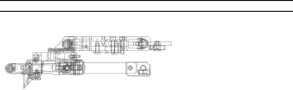
Mechanical
Bonding mechanism is constructed of four axes, straight-line and orthogonal, stacked in an array. Two
axes, X and Y, are driven by micromanipulator for positioning, then held by pneumatic brakes for bonding.
Two axes, W (in Y direction) and Z, are driven by programmed motors to create and arch the connection.
The vertical view video camera is mounted atop the X-Y axes so that the manipulator moves its target
crosshairs. When video method is chosen, the tool is withdrawn along the W axis during alignment.
When aligning by microscope, target is judged by an angled view of the tool at a search elevation just
above the work. Approach to search and then down to contact can be controlled by a separate manual
encoder that generates clocks to drive the Z Motor directly, or can be controlled at the keypad or by a
push-button on the right-hand control. These different methods can be used interchangeably in any
sequence. Similarly, alignment by microscope or video is optional. Video alignment allows bonding of
the entire connection after a single input accepting the targeting of the critical bond, though requiring
extra runs on the W axis to hide the tool. Microscope alignment allows direct view of and placement of all
bonds with minimum movements. The work piece is aligned front-to-back on a large platform that is fully
adjustable through the bond plane. Alignment can be checked before bonding by scanning methods. The
work platform is also adjustable in elevation.
Ranges, Ratios, and Resolutions
• X-Y Positioning, by Manipulator 0.625" Total, +/- 0.3125" @ 8/1 Ratio
• Y Stroke (W axis), by Motor 0.500" Total, 0.200" Forward, 0.300" Rearward from target point
• Maximum Bond Span 0.299” Maximum wire length
• Resolution 0.00333" per half-step, 0.000208" per micro-step
• Z Stroke, by Motor 0.500" Total, 0.460" Up, 0.040" Down
• Resolution 0.00333" per half-step, 0.000208" per micro-step
• Z Encoder, Manual 0.125" Touchdown from Search @ 8/1 Ratio
• Resolution 0.001" per encoder transition
• Work Platform, by Thumbscrew 0.730" Total, 0.140" Above, 0.590" Below
(measurements made with respect to bond height)
WEST•BOND MODEL 454647E SERIES INSTRUCTION MANUAL
3
PRODUCT OVERVIEW
Bond Tool Head Assemblies
The new forward-pivot tool assemblies
of this series are built around K~Sine
Transducer, Model No. 24-W, operated
at 63 KHz. It is driven by K~Sine Part
No. 10345 Ultrasonic Power Supply,
four Watts, dual channel, with power
and time set as program values. This
transducer uses a bond tool length of
0.750". Vertical clearance is a full
0.375" everywhere under these tool heads and all other mechanism except for wire presentation at 45°
for angled feed. Wire Clamps are air-opened and spring-closed, and have self-contained closure pivots. A
separate pivot about an axis located to serve both overhead and angled feed generates the clamp
motions along their lines of feed action. To change between angled feed and overhead feed, it is
necessary only to exchange the small clamp assemblies and to change the wire drag means. Alignment
of clamps to the tool is facilitated by individual adjustments along three axes. Actuation of all clamp
motion is by the same spiral cam of an inboard motor and is transferred through the pivots of the four-bar
linkage. Appropriate clamp motion settings for each method are configured in software and are retained in
non-volatile memory. Motions toward the tool are spring-driven, while the more powerful motor drives
away from the tool – to ease concerns during set-up.
Rigid bearing mounts, rather than taper loading, fix the strut bar of this assembly so that any required
bond force can be applied. The standard set of force springs generates 15 to 250 grams, and together
with the work-sensing firing switch, is built into the four-bar linkage. A dual force mechanism, operated
pneumatically, acts to change between two pre-set force values, and either high or low force may be
programmed for any bond. Radiant tool heat with panel mounted, constant current control is included.
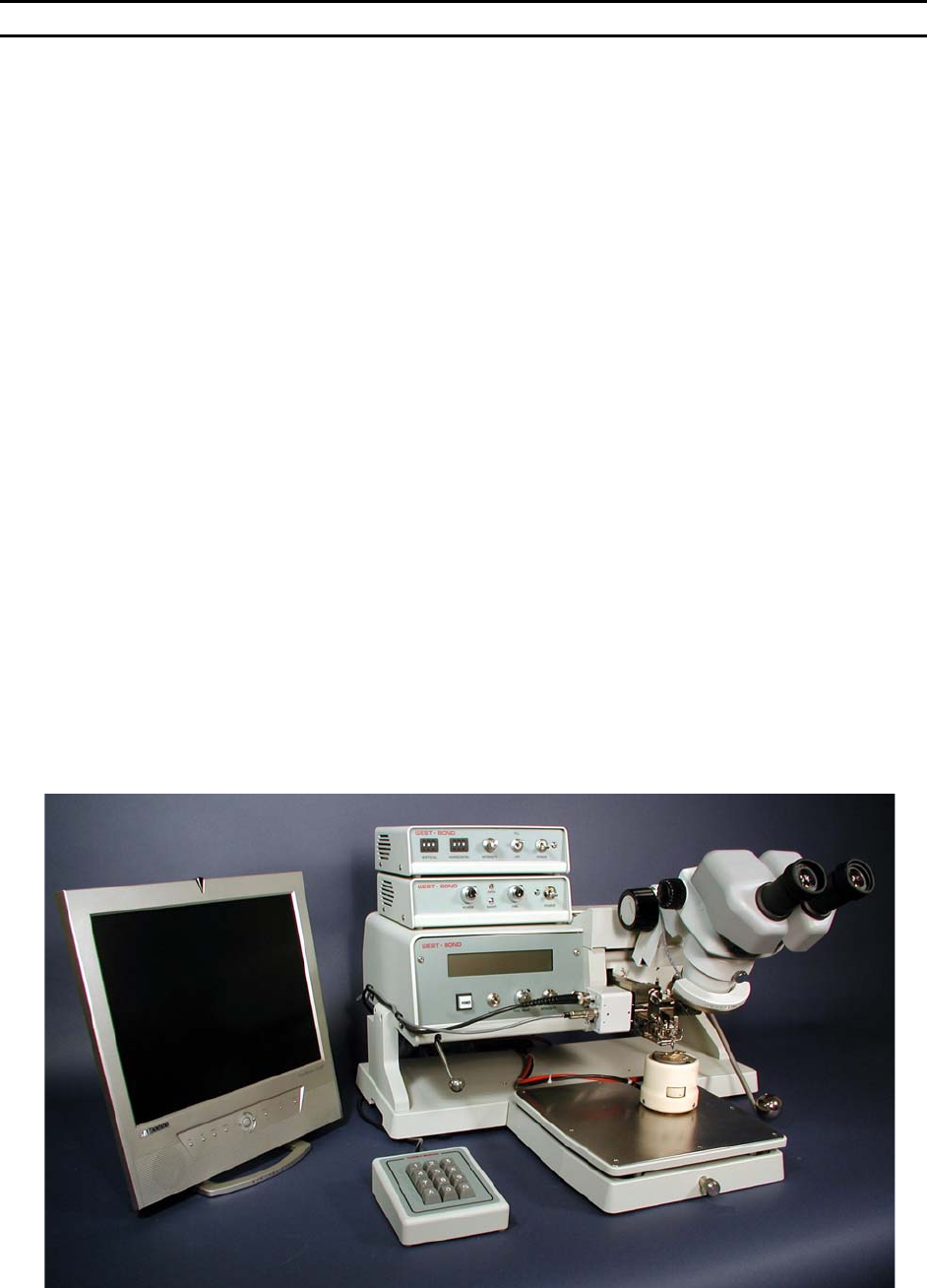
Machine Configuration
The mechanism of this series was designed to mount above a customer's work handling system, to be
confined entirely above the work plane, and so not to have any base or work platform. In this
configuration, a model of this series is designated as "454647EX". For use as a stand-alone complete
bonding machine, the mechanism will be completed with a plain base having a bolted-on, adjustable
height, work platform, and will be designated as "454647E". In either the "E" or the "EX" configurations,
optional control arms are included to move both the manipulator control point and the Z axis encoder
control point five inches vertically from their normal positions near the machine base to new locations
above the work plane. When the high control arrangement is used, the customer must provide suitable
operator's forearm rests. This is essential both for the operator's safety and comfort, and to provide a
stable platform from which to direct control motions with the accuracy required for wire bonding. The
manual Z Encoder method of controlling tool descent is optional.
Mounting points for the "EX" version of this mechanism are provided at two foot locations at the work
plane elevation, approximately 22.312 in. apart, and 8.734 in. to the rear left, and 13.093 in. rear right, of
the work point.
Electrical Software and Hardware
A software program controls operation of motors and other actuators, as configured by setup values, in
response to operator’s inputs. It accepts entry of data about User’s Devices to create different Types of
connections. These Types may have any number of Bonds, up to 100, and may be repeated for any
number of Wires up to the maximum of 6000 individual Bonds. Data to define all the motions required to
create the connections are stored in Buffers that are selected by the keypad. Default values are 30