wire-bonder.pdf - 第47页
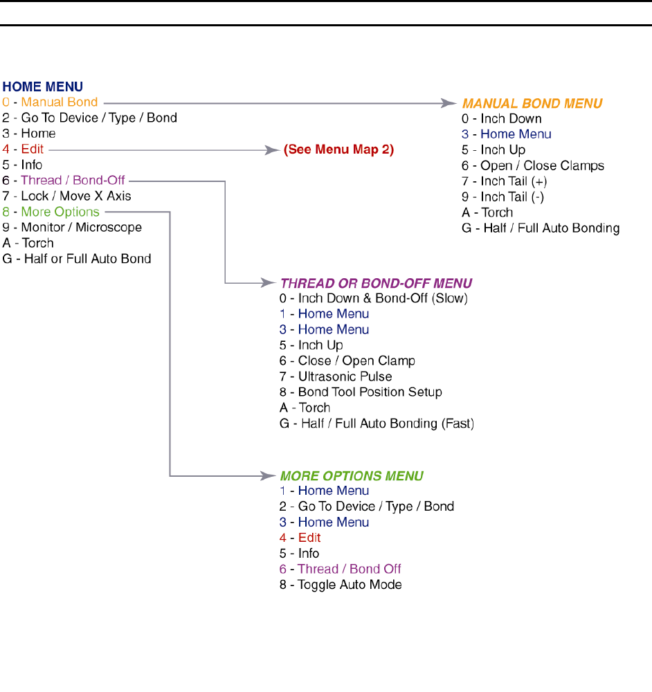
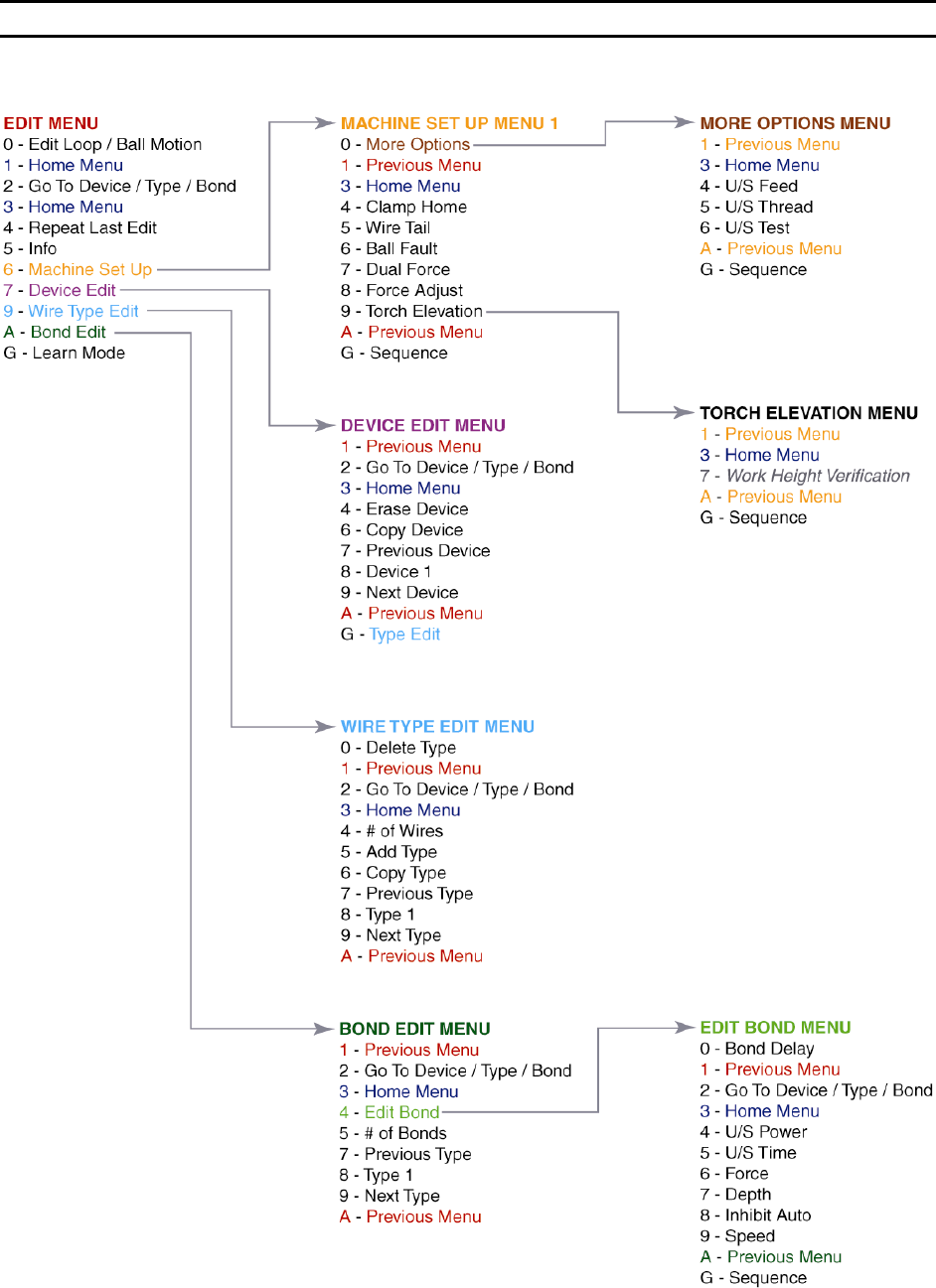
WEST•BOND MODEL 454647E SER IES INSTRUCTION MANUAL 41 MENU MAP Model 4700E (continued)
WEST•BOND MODEL 454647E SERIES INSTRUCTION MANUAL
40
MENU MAP
Model 4700E
WEST•BOND MODEL 454647E SERIES INSTRUCTION MANUAL
41
MENU MAP
Model 4700E (continued)

WEST•BOND MODEL 454647E SERIES INSTRUCTION MANUAL
42
PROGRAMMING
The following pages demonstrate the expected displays and programmable options of the 454647E. The
programmable features are broken into two sections: One section is called M
ACHINE SETTINGS and the
other is called U
SER DATA SETTINGS.
Machine Settings
These are items generally used for initial machine set-up and are infrequently changed. Options in this
section may require some modification if the application changes significantly. Here are the options
available for programming in this section:
1. C
LAMP HOME – page 54
2. W
IRE PULL – page 55
3. W
IRE TAIL – page 56
4. B
ALL FAULT – page 57
5. D
UAL FORCE – page 58
6. F
ORCE ADJUST – page 59
7. R
ESTART HEIGHT – page 61
8. L
IFT-TO-PULL – page 62
9. U
LTRASONIC POWER DURING FEED – page 63
10. U
LTRASONIC POWER DURING THREAD – page 64
11. U
LTRASONIC DIAGNOSTIC TEST – page 65
User Data Settings
These are options commonly used by the operator. For this reason they have been separated from the
M
ACHINE SETTINGS and stored into DEVICES, WIRE TYPES, or BONDS. Each device allows one or more wire
types. Each wire type allows one or more bonds. Here are the options available for programming in this
section:
1. D
EVICE EDIT – page 68
2. W
IRE TYPE EDIT – page 71
3. B
OND EDIT – page 79
The D
EVICE EDIT MENU is designed to do the following tasks:
a. C
OPY DEVICE – page 70
b. E
RASE DEVICE – page 69