9018-18076.pdf.pdf - 第26页
4-2 Site Preparation 4 RF Attenuation Requirements Introduction This chapter describes the installation requirem ents and possible solutions where additional RF attenuation measures are required as part of the ins tallat…

4-2 Site Preparation
4 RF Attenuation Requirements
Introduction
This chapter describes the installation requirements and possible solutions where additional RF
attenuation measures are required as part of the installation. The limits for the radiated RF emissions
are set by various standards such as CISPR 11, an international standard, ICES-001 for Canada, EN
61326 for the EU and the Radio communications (Electromagnetic Compatibility) Standard 2001 for
Australia.
The Target Site Attenuation, meaning the required attenuation to be provided by the site for the
installation, is 15 dB for Medalist i3070 systems. Some sites are permitted radiated RF emissions
higher than allowed for individual products. For example, in the EU a local PTT agency may provide
for a Site Allowance. If a Site Allowance is permitted, subtract the Site Allowance from the Target Site
Attenuation and this becomes the Required Site Attenuation.
The Available Site Attenuation of a specific installation can be calculated as shown in Calculating Site
Attenuation. Consider the location of existing walls as well as installing additional walls when
considering the possible locations for the installation. After choosing the installation location and
determining any additional needed site preparations, compute the Available Site Attenuation for this
installation.
In the event that the Available Site Attenuation for this installation is not greater than or equal to the
Required Site Attenuation, consider the use of a Shielded Cabin with specified shielding performance.
Other shielding methods such as conductive wallpaper, metallized walls, etc. may be used. These
methods may require an approval test. This test, called in situ testing, may need to be performed by
an authorized agency or an organization designated by an authorized agency.
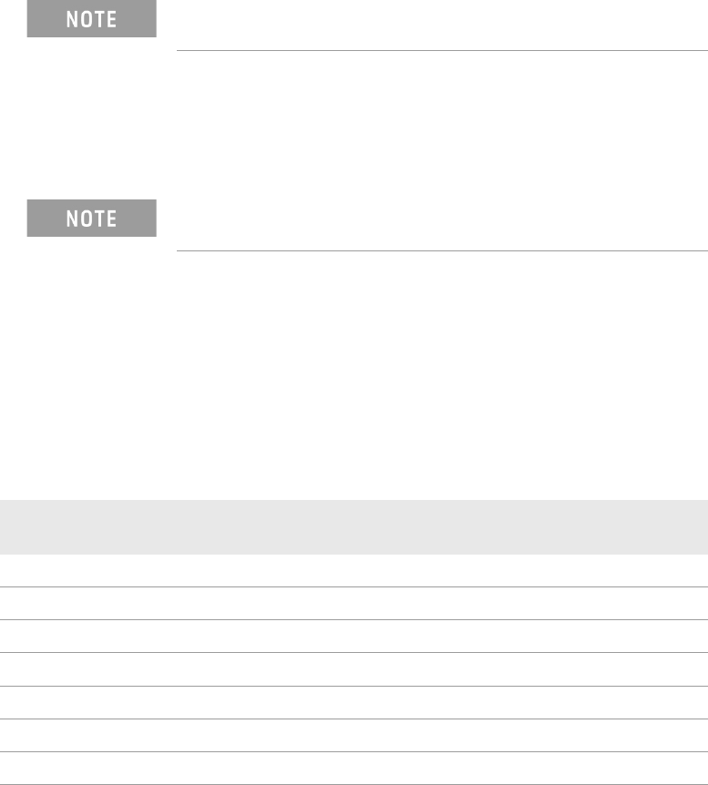
Table 4-5 shows the results of using calculating the required site attenuation with no site allowance.
D = 30log
-1
((R - 10 * n) / 20);
where R = (10 * n), else D = 30 m
When the Medalist ICT system is testing a device under test (DUT) the RF emission
levels may increase because the DUT will also be radiating RF energy.
The Available Site Attenuation for this installation must be greater than or equal to the
Required Site Attenuation.
Table 4-5 Determining Available Site Attenuation without a site allowance
R; Required Site
Attenuation (dB)
n; Number of
Concrete Walls
Remaining Attenuation
Requirement (dB)
D; Distance from Equipment to
Real Estate Border (m)
UnMux systems
10 0 10 95
10 1 0 30
Mux systems
15 0 15 170
15 1 5 55
15 2 0 30
RF Attenuation Requirements 4
Site Preparation 4-3
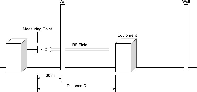
Calculating Site Attenuation
To obtain the necessary attenuation at the installation site you can increase the distance between the
equipment and the property boundary or you can add walls or other attenuating structures:
• Required Site Attenuation (R)
R = Target Site Attenuation – Site Allowance
Where:
• Target Site Attenuation = 15 dB
• Site Allowance for your site = ____________
• The distance from the equipment to the property boundary (D) can be calculated as follows:
D = 30 or 30*log
-1
((R – n * W)/20) whichever is greater.
Where:
• R = Required Site Attenuation
• n = Number of concrete walls between equipment and property boundary.
• W= Attenuation of the wall (a concrete wall without openings has an attenuation of 10 dB)
• Additional attenuation (X) due to a D greater than 30 meters.
X = 20log(D/30)
Where:
• D = distance from equipment to property boundary.
• Total attenuation (A) is calculated as follows:
A = X + n * W
Where:
• X = Additional Attenuation
• n = Number of concrete walls between equipment and property boundary.
• W= Attenuation of the wall (a concrete wall without openings has an attenuation of 10 dB)
Figure 4-3 Determining Available Site Attenuation