9018-18076.pdf.pdf - 第65页
Compressed Air and Vacuum Requirements 7 Site Preparation 7-7 Compressed Air and Vacuum Primer There are two key concepts involved in understan ding the compressed air and vacuum requirements for the i3070. The first is …
7-6 Site Preparation
7 Compressed Air and Vacuum Requirements
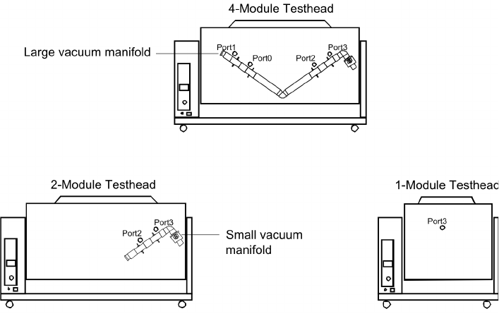
Connecting Vacuum to the Testhead
Figure 7-31 shows the vacuum port locations on the system. The vacuum manifolds shown are
optional.
Figure 7-31 Vacuum port locations
Large vacuum
manifold
Small vacuum
manifold
Compressed Air and Vacuum Requirements 7
Site Preparation 7-7
Compressed Air and Vacuum Primer
There are two key concepts involved in understanding the compressed air and vacuum requirements
for the i3070. The first is pressure and the second is flow rate.
Pressure is the force per unit area that a gas exerts on a surface. If zero is used as a reference, the
measurement of pressure is called “absolute”; if the local atmospheric pressure is used as a reference,
the measurement is called “gage.” Although atmospheric pressure varies with altitude and weather,
gage pressure is typically used for engineering measurements, so it is used in this manual. A pressure
value below zero gage is considered a vacuum.
Common units for measuring pressure are kilopascals (kPa), pounds per square inch (psi), and
atmospheres (atm).
Flow rate is the quantity of a gas moving through a given area per unit of time. Since air is
compressible, you must know both the speed and pressure of the air when measuring the flow rate.
To reduce confusion, the industry has agreed on a standard set of conditions for flow rate
measurements called “standard temperature and pressure” (STP). The standard temperature is 0°C
(32°F), and the standard pressure is one atmosphere (101.3 kPa or 14.7 psi).
Common units for measuring flow rate are liters per second (l/s) and cubic feet per minute (CFM).
When using standard conditions, the units are written as “l/s at STP” or “SCFM” (standard cubic feet
per minute).
Compressed Air
The i3070 uses compressed air to activate both the fixture pull-down towers and the vacuum valves.
The system also provides an outlet for supplying air to accessory equipment such as handlers and air
assisted fixtures.
The minimum pressure needed is 480 kPa (70 psi). The system has an internal regulator to restrict the
maximum pressure inside the system to 550 kPa (80 psi).
The flow rate needed is dependent on how often fixtures are changed, but is generally much less than
what is available in most production areas. Additional air (flow rate) may be needed to supply the
outlet for custom fixtures or presses depending on their requirements.
7-8 Site Preparation
7 Compressed Air and Vacuum Requirements
Vacuum
The system doesn’t use vacuum directly. Rather, the vacuum is used by the fixture to pull a device
under test (DUT) onto the probes. The system provides valves, plumbing and control to assist in
supplying vacuum to the customer’s fixture.
The pressure requirements for vacuum come from the need to compress the probes, fixture springs
and seals. Since most commercial vacuum systems operate around 50 kPa (7.5 psi), vacuum fixtures
are limited in their ability to handle DUTs with high probe densities. If the sum of the probe, spring and
seal forces divided by the area of the DUT is above 48 kPa (7 psi) the fixture will not be able to properly
pull the DUT onto the probes.
The flow requirements for vacuum come from fixture leaks, number of fixture cycles per minute, the
size of the DUT and the need to quickly evacuate the fixture to make a good seal around the DUT. Due
to the variability of these factors, it is difficult to provide an exact flow rate recommendation. Keysight
has found that a flow rate of 19 l/s (40 SCFM) will pull down most fixtures.