9018-18076.pdf.pdf - 第35页
Power Requirements 6 Site Preparation 6-3 About the PDU The testhead product number and serial number are located on the rear of the testhead cradle. Figur e 6-4 and Figur e 6-5 show rear views of the systems. The PDU (P…

6-2 Site Preparation
6 Power Requirements
Customer Responsibilities
It is the customer’s responsibility to (a) prepare the site with adequate AC power for the system, and
(b) connect the system to the AC power source. These are not Keysight’s responsibilities.
6 Read About the PDU on page 6-3. You must know where the system’s PDU is located to prepare
your site.
7 Read Power Requirements on page 6-4. In most cases this section will describe all you need to
do to prepare your site.
8 If you are connecting the system to a different power configuration than it is wired for, read Is
PDU Re-wiring Necessary? on page 6-9.
After connecting power to the system, do not power up the system. A Keysight service
representative will verify the power and complete the system installation and
verification.
Power Requirements 6
Site Preparation 6-3
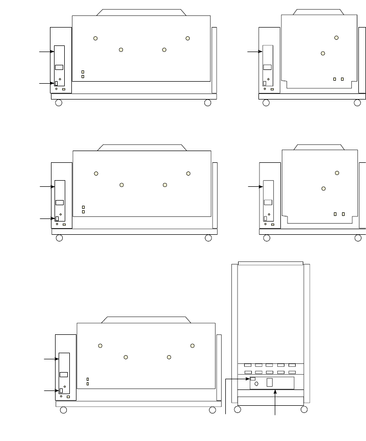
About the PDU
The testhead product number and serial number are located on the rear of the testhead cradle.
Figure 6-4 and Figure 6-5 show rear views of the systems.
The PDU (Power Distribution Unit) is the device in the system to which you will connect AC power.
The PDU is wired differently for different power configurations. The voltage of the PDU is marked on
the front panel of the PDU. If you install a system in a location in which the actual power does not
match the power configuration of the PDU, you may need to rewire the outlet connections in the PDU
(see Is PDU Re-wiring Necessary? on page 6-9).
Figure 6-4 Rear views of the UnMux system
Figure 6-5 Rear views of the Mux system
PRGXOH7HVWKHDG
3RUW
3RUW
,QXW
3'8
RUPRGXOH7HVWKHDG
0DLQV
'LVFRQQHFW
3RUW
3RUW
3RUW
3RUW
,Q
XW
3'8
3'8%UDQFK
6LQJOHSKDVHRSWLRQVZLWK
SKDVHYROWDJHOHVVWKDQ9
9LHZZLWKUHDU
GRRURSHQ
PRGXOH7HVWKHDGZLWK6XSSRUW%D\
0DLQV
'LVFRQQHFW
3RUW
3RUW
3RUW
3RUW
,Q
XW
3'8
0DLQV
'LVFRQQHFW
PRGXOH7HVWKHDG
3RUW
3RUW
,QXW
3'8
PRGXOH7HVWKHDG
0DLQV
'LVFRQQHFW
3RUW
3RUW
3RUW
3RUW
,Q
XW
3'8
6-4 Site Preparation
6 Power Requirements
Power Requirements
• Mains Disconnect
• Power Drop
• Basic Power Quality Survey
• Connecting Power to the PDU
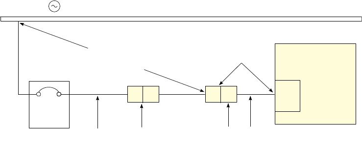
Mains Disconnect
A mains disconnect — providing over-current and short-circuit protection — must be provided for the
system. It may be a fused disconnect or a circuit breaker (see Figure 6-6).
If a fused disconnect is used, it must:
• Be rated for 30 amps in each phase.
• Open all line conductors and neutral conductors where local code applies, but not the protective
earth conductor.
• Be marked “System Mains Disconnect” or the equivalent in your local language
• Be marked with a “|” for the “On” position or “O” for the “Off” position.
• Be capable of being locked in the “Off” position, but not in the “On” position.
• Be installed within 3 meters of the system, where it can be easily reached by the system operator
without requiring the system to be moved to access the disconnect.
If a circuit breaker is used, it must meet all of the above requirements plus:
• Be rated for a minimum of 10,000 amps interrupting capacity (AIC) if used on a 200–240 volt
circuit, or 14,000 AIC if used on a higher voltage circuit.
Figure 6-6 Wiring diagram
6\VWHP
&LUFXLW
%UHDNHU
RU)XVHV
3'8
$&YROWDJHVRXUFH
3RZHUUHFHSWDFOHDQG
SRZHUFRUGIURP3'8
(OHFWULFLDQ
PXVWGHWHUPLQH
WKHFRQGXFWRUVL]H
&XVWRPHULQVWDOOHGSRZHU
GURSDQGUHFHSWDFOH
0DLQV
'LVFRQQHFW
9ROWDJHPHDVXUHGDWWKH
SRZHUUHFHSWDFOHRU3'8
ZLWKWKHV\VWHPRQPXVWEH
RIQRPLQDO