9018-18076.pdf.pdf - 第37页
Power Requirements 6 Site Preparation 6-5 Power Drop • A dedicated power drop must be pr ovided for the testhead due to its high current r equir ements. • Copper wir e must be used for the power dr op. • An electrician m…
6-4 Site Preparation
6 Power Requirements
Power Requirements
• Mains Disconnect
• Power Drop
• Basic Power Quality Survey
• Connecting Power to the PDU
Mains Disconnect
A mains disconnect — providing over-current and short-circuit protection — must be provided for the
system. It may be a fused disconnect or a circuit breaker (see Figure 6-6).
If a fused disconnect is used, it must:
• Be rated for 30 amps in each phase.
• Open all line conductors and neutral conductors where local code applies, but not the protective
earth conductor.
• Be marked “System Mains Disconnect” or the equivalent in your local language
• Be marked with a “|” for the “On” position or “O” for the “Off” position.
• Be capable of being locked in the “Off” position, but not in the “On” position.
• Be installed within 3 meters of the system, where it can be easily reached by the system operator
without requiring the system to be moved to access the disconnect.
If a circuit breaker is used, it must meet all of the above requirements plus:
• Be rated for a minimum of 10,000 amps interrupting capacity (AIC) if used on a 200–240 volt
circuit, or 14,000 AIC if used on a higher voltage circuit.
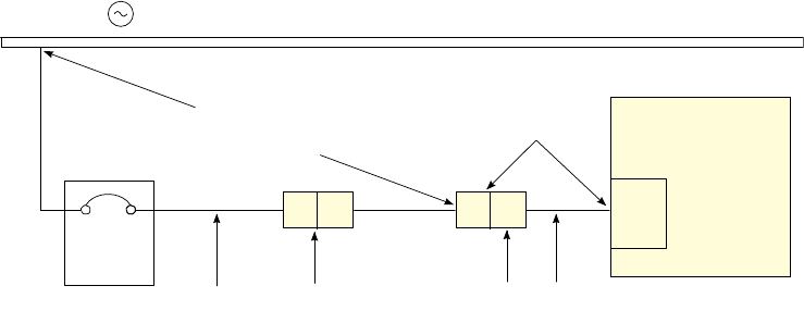
Figure 6-6 Wiring diagram
6\VWHP
&LUFXLW
%UHDNHU
RU)XVHV
3'8
$&YROWDJHVRXUFH
3RZHUUHFHSWDFOHDQG
SRZHUFRUGIURP3'8
(OHFWULFLDQ
PXVWGHWHUPLQH
WKHFRQGXFWRUVL]H
&XVWRPHULQVWDOOHGSRZHU
GURSDQGUHFHSWDFOH
0DLQV
'LVFRQQHFW
9ROWDJHPHDVXUHGDWWKH
SRZHUUHFHSWDFOHRU3'8
ZLWKWKHV\VWHPRQPXVWEH
RIQRPLQDO
Power Requirements 6
Site Preparation 6-5
Power Drop
• A dedicated power drop must be provided for the testhead due to its high current requirements.
• Copper wire must be used for the power drop.
• An electrician must determine the wire size for the power drop. The wires must be sized to ensure
that the voltage at the system does not drop below 90 percent of nominal (see Calculating the
Minimum Voltage on page 6-5).
• Convenience outlets should be provided near the system for external equipment such as
programming stations, extra equipment bays, and automation equipment. Locate the outlets
within one meter (three feet) of the rear of the system. See Chapter 2, Planning to plan the
location of convenience outlets. Convenience outlets should supply current protection at 15A or
20A depending on local code requirements at 100–120 volts or current protected at 10A
depending on the local code requirements at 200–240 volts.
Calculating the Minimum Voltage
The voltage at the testhead must be at least 90 percent of nominal. To calculate the minimum rms
voltage multiply the rms voltage by 0.9. To calculate the minimum peak voltage, multiply the rms
voltage by 0.9 and then 1.414. For example:
208 volts rms * 0.9 * 1.414 = 265 volts peak

6-6 Site Preparation
6 Power Requirements
Sizing the Input Wires and Circuit Breakers
Table 6-9 shows the full-load amps (FLA) for each system type.
Table 6-9 Power requirements
PDU Power
Option
Frequency Vol tage
line-to-neut /
line-to-line
Full-Load Amps (FLA) for:
1-module
system
2-module
system
4-module
system
200–240V 3-Phase Delta 3PD 50/60 hertz 200
220
230
240
13
13
13
13
18
18
18
18
24
24
24
24
208–220V 3-Phase Wye 3PY 50/60 hertz 208
220
13
13
18
18
24
24
380–415V 3-Phase Wye with
Neutral
3PN 50/60 hertz 220 / 380
230 / 400
240 / 415
9
9
9
10
10
10
16
16
16
/
/
/
*
1RSWLRQDO
/
/
/
*
1RSWLRQDO
/
/
/
*
1
Neutral is not used by the systems for power options 3PD and 3PY. Neutral is shown in
the diagrams because Neutral is cabled into the PDU.