9018-18076.pdf.pdf - 第38页
6-6 Site Preparation 6 Power Requirements Sizing the Input Wires and Circuit Breakers Ta b l e 6 - 9 shows the full-load amps (F LA) for each system type. Ta b l e 6 - 9 Power requir ements PDU Power Option Frequency Vol…
Power Requirements 6
Site Preparation 6-5
Power Drop
• A dedicated power drop must be provided for the testhead due to its high current requirements.
• Copper wire must be used for the power drop.
• An electrician must determine the wire size for the power drop. The wires must be sized to ensure
that the voltage at the system does not drop below 90 percent of nominal (see Calculating the
Minimum Voltage on page 6-5).
• Convenience outlets should be provided near the system for external equipment such as
programming stations, extra equipment bays, and automation equipment. Locate the outlets
within one meter (three feet) of the rear of the system. See Chapter 2, Planning to plan the
location of convenience outlets. Convenience outlets should supply current protection at 15A or
20A depending on local code requirements at 100–120 volts or current protected at 10A
depending on the local code requirements at 200–240 volts.
Calculating the Minimum Voltage
The voltage at the testhead must be at least 90 percent of nominal. To calculate the minimum rms
voltage multiply the rms voltage by 0.9. To calculate the minimum peak voltage, multiply the rms
voltage by 0.9 and then 1.414. For example:
208 volts rms * 0.9 * 1.414 = 265 volts peak

6-6 Site Preparation
6 Power Requirements
Sizing the Input Wires and Circuit Breakers
Table 6-9 shows the full-load amps (FLA) for each system type.
Table 6-9 Power requirements
PDU Power
Option
Frequency Vol tage
line-to-neut /
line-to-line
Full-Load Amps (FLA) for:
1-module
system
2-module
system
4-module
system
200–240V 3-Phase Delta 3PD 50/60 hertz 200
220
230
240
13
13
13
13
18
18
18
18
24
24
24
24
208–220V 3-Phase Wye 3PY 50/60 hertz 208
220
13
13
18
18
24
24
380–415V 3-Phase Wye with
Neutral
3PN 50/60 hertz 220 / 380
230 / 400
240 / 415
9
9
9
10
10
10
16
16
16
/
/
/
*
1RSWLRQDO
/
/
/
*
1RSWLRQDO
/
/
/
*
1
Neutral is not used by the systems for power options 3PD and 3PY. Neutral is shown in
the diagrams because Neutral is cabled into the PDU.
Power Requirements 6
Site Preparation 6-7
Basic Power Quality Survey
Power quality can affect system performance differently. The following procedure is intended as a
guideline and may not be the total solution. Failure to meet these guidelines should serve as an
indicator that a power quality consultant might be needed to conduct a more in-depth power quality
survey.
1 With the system operating, measure harmonic distortion at the system-input connection. THD
should be less than 5% and less than 3% for any single harmonic.
2 With the system operating, measure the ground-to-neutral voltage at the system-input
connection; the voltage should be less than 4vp-p.
3 Turn the system power off and measure the line voltage at the system-input connection; record
this reading. Turn the system on and begin operating mode. Measure the line voltage at the
system-input connection again. The difference between the two measurements should be less
than 2%.
Other problematic power qualities include momentary voltage interruptions, ground noise, and
voltage spikes. A survey of these problems and others may require the services of a power quality
expert with specialized equipment.
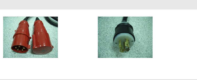
Connecting Power to the PDU
One of two different power cords and plugs are attached to the PDU depending on the country where
the system will be installed.
Table 6-10 Power cord and plugs
International North America
Uses 5 x 6 mm
2
5-conductor cord with a IEC
60309 plug and mating receptacle.
See Figure 6-7 on page 6-8.
Uses #10 AWG 5-conductor cord with NEMA plug that
mates with NEMA L21-30. See Figure 6-8 on page 6-8.
The female receptacle is available locally.