00192485-02.pdf - 第10页
10 Machine A reas The figure below pro vides a diag rammatic overview of th e individu al areas of a SIPLA CE place ment station. The terms used in th e figure to de scribe th ese areas are also used in the texts in the …

9
The entries in the table next to "flashes" refer to the frequency with which
the relevant lamp flashes for a given event.
The entry (1, 5), for example, can be explained as follows:
– The first number in the brackets indicates the time, expressed in 100 msec
intervals, for which the fault indicator lamp is switched on,
i.e. 1 x 100 msec in the above example.
– The second number in the brackets indicates the time, expressed in 100
msec intervals, for which the fault indicator lamp is switched off, i.e. 5 x
100 msec in the above example.
L1 (white)
(Top lamp)
L2 (green)
(Middle lamp)
L3 (white)
(Bottom lamp)
Meaning
Status display
flashes (1,10) flashes (7,7) flashes (1,10) Reference run
unchanged flashes (1,5) unchanged Waiting until axes in position
unchanged flashes (7,7) unchanged Waiting for setup data
unchanged flashes (7,7) unchanged Waiting for cluster data
unchanged flashes (7,7) unchanged Load table program
unchanged flashes (7,7) unchanged Position recognition
unchanged flashes (1,10) unchanged Ink spot recognition
unchanged flashes (7,7) unchanged Nozzle configuration test
unchanged flashes (7,7) unchanged Feeder posn. recogn.
unchanged flashes (7,7) unchanged One track is empty
unchanged flashes (7,7) unchanged No further track available
unchanged flashes (7,7) unchanged Go to refill position
unchanged flashes (7,7) unchanged Transport being initialized
unchanged flashes (7,7) unchanged Place PCB in input conveyor
flashes (1,10) flashes (7,7) unchanged
Remove PCB from output con-
veyor
unchanged flashes (7,7) flashes (1,10)
Remove PCB in output conveyor
2
flashes (1,10) flashes (7,7) flashes (1,10) Width adjustment
unchanged flashes (1,10) unchanged Transport PCB
flashes (1,10) flashes (7,7) flashes (1,10)
Both output conveyors are
cleared
on flashes (1,10) on Transport errors
on off on Go to service position
on Placement
flashes (1,20) Waiting for processing data
Error display
on off unchanged Machine error, right
on off unchanged Track empty, right
on off unchanged Nozzle configuration, right
on off unchanged Transport error, right
on off on Fiducial error, left and right
on off on Fiducial error, left and right
unchanged off on Track empty, left
unchanged off on Nozzle configuration, left
unchanged off on Transport error, left
unchanged off on Machine error, left
Pick-up error display
unchanged unchanged flashes (1,20) First track empty, left
unchanged unchanged flashes (5,20) Further tracks empty, left
unchanged unchanged flashes (5,5) Penultimate track in use, left
unchanged unchanged flashes (1,2) Last track in use, left
flashes (1,20) unchanged unchanged First track empty, right
flashes (5,20) unchanged unchanged Further tracks empty, right
flashes (5,5) unchanged unchanged Penultimate track in use, right
flashes (1,2) unchanged unchanged Last track in use, right

10
Machine Areas
The figure below provides a diagrammatic overview of the individual areas
of a SIPLACE placement station.
The terms used in the figure to describe these areas are also used in the
texts in the user interface and in the User Manual.
The PCB conveyor is divided into the following sections:
– Input conveyor
– Processing conveyor 1 (PC1)
– Intermediate conveyor
– Processing conveyor 2 (PC2)
– Output conveyor
Direction of transport
Input
area
Location 3
Location 1
Location 2
Gantry 4
Gantry 3
Gantry 2
Gantry 1
Conveyor 2
(left)
Conveyor 1
(right)
Location 4
Processing
area PC1
Intermedi-
ate area
Processing
area PC2
Output
area
11
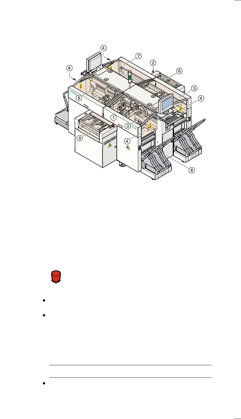
Safety devices
Emergency stop mushroom-head push-buttons
If serious problems occur:
The placement system will stop immediately. Attempt to
eliminate the problem. If this is not possible, call the line
engineer.
Continue processing
Turn the emergency stop mushroom-head push-button to the left to
release it.
Press the Start key.
Protective covers
Make sure that all covers are closed when the machine is operating. As
soon as a cover is opened, the machine will stop and an error message of
the following type may be displayed during placement:
General error: 270 PCB interrupted due to EMERGENCY STOP
Transp.: 1 DEV:1 #E:1
Close the covers and press the Start key.
a Emergency stop mushroom-head push-button, input side
s Emergency stop mushroom-head push-button, output side
d Protective cover, input side, right
f Front panel
g Protective cover, output side, right
h Guard, output side
j Protective cover, output side, right
k Protective cover, input side, left
l Guard, input side
Á
F