00192485-02.pdf - 第6页
6 Main switc h The main s witch is u sed to switch the powe r supply to the placement s ys- tem on and off. RISK OF DE A TH Certain parts inside the p lacemen t system contin ue to ca rry potentially lethal voltages even…
5
Abbreviations
The following abbreviations are employed in this quick reference guide:
#E Error counter
BC Barcode
BE, Cmp, CO Component
DEV Originator of the error
GF Package form
IC Input conveyor
IC Intermediate conveyor
OC Output conveyor
PC1 Processing conveyor 1
PC2 Processing conveyor 2
PCB, LP Printed circuit board
Seg Segment
SF Single functions
TR/D/T Track/Division/Tray
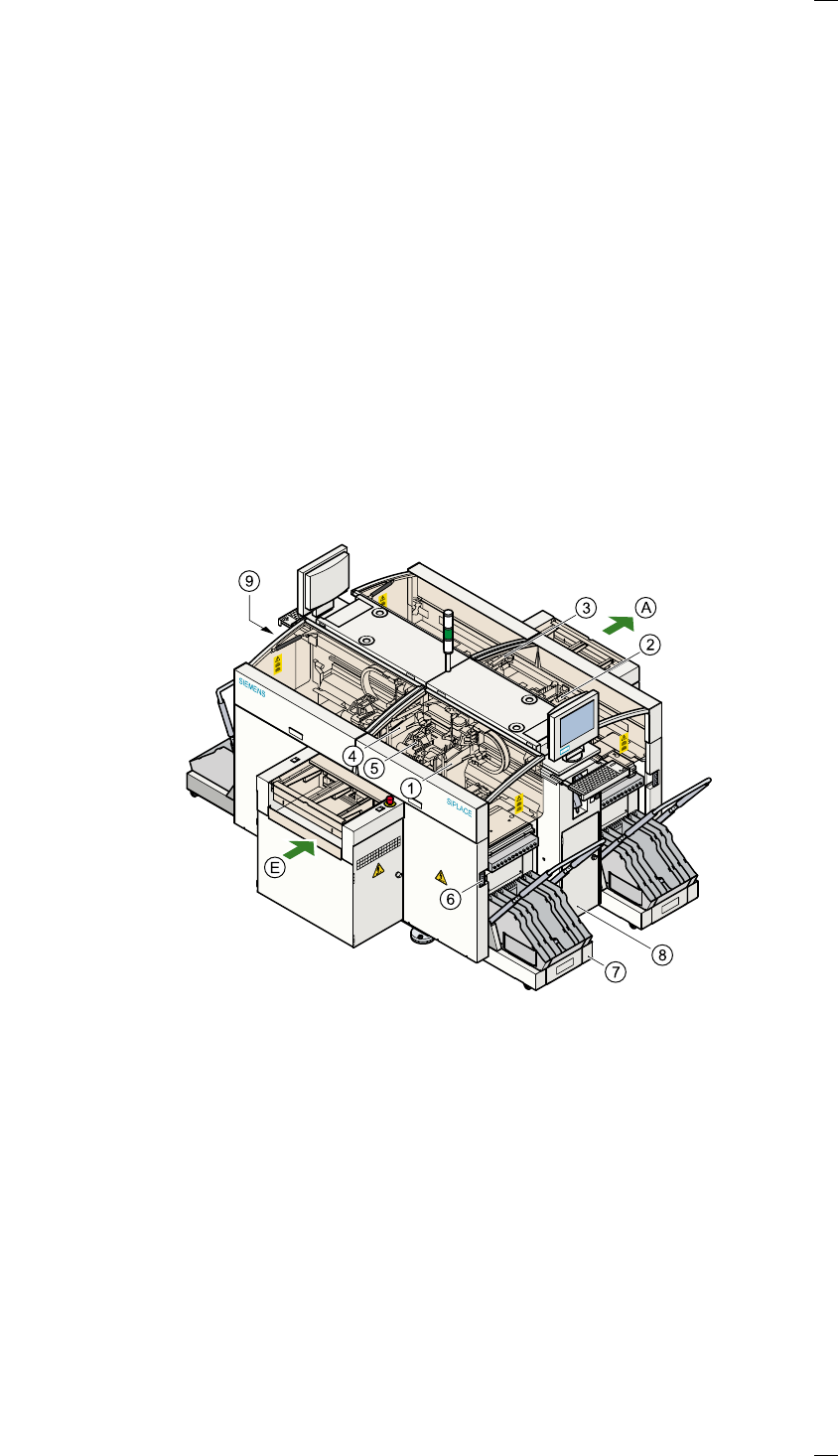
Structure of the placement system
Switches and buttons on the placement system
The following diagram shows the positions of the switches and buttons on
the placement system.
a Gantry 1 j Component changeover table
s Gantry 2 k Controls, right (pneumatic system)
d Gantry 3 l Controls, left (electrical system)
f Gantry 4
g 12-segment Collect&Place head A PCB conveyor - output side
h Socket for the component
changeover table cable
E PCB conveyor - input side
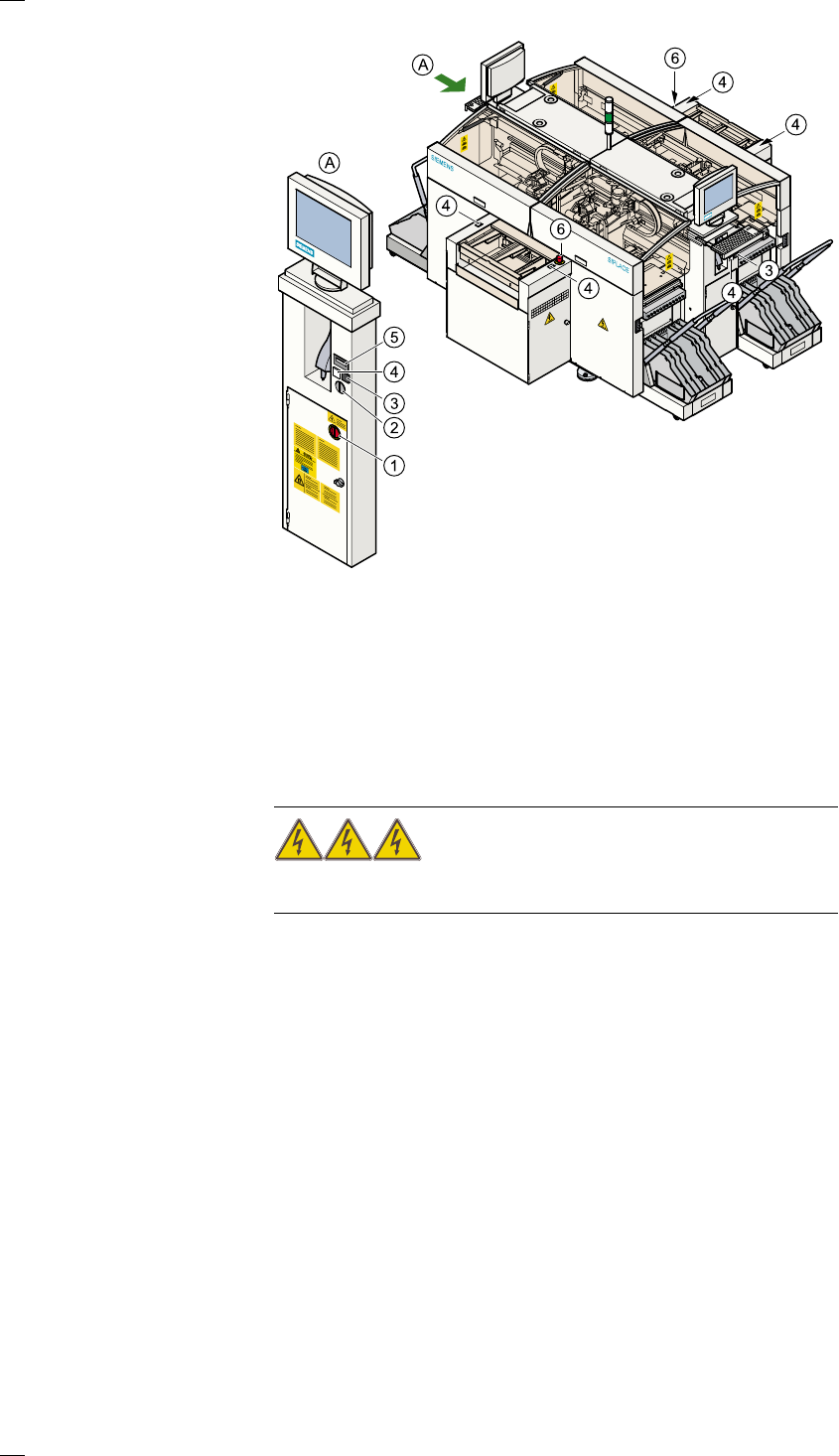
6
Main switch
The main switch is used to switch the power supply to the placement sys-
tem on and off.
RISK OF DEATH
Certain parts inside the placement system continue to carry potentially
lethal voltages even when switched off at the main switch.
Key switch
The key switch is normally set to the "0" position during operation. The key
should be removed and kept in a safe place. Only authorized personnel
may turn it to the "I" position (line engineer mode), and then only for cer-
tain maintenance or servicing work.
Stop button
This button is used to stop placement on the placement system.
Start button
Use this button to start the placement system after switching on or elimi-
nating a fault.
Emergency stop mushroom-head push-button
The emergency stop mushroom-head push-button latches in place when it
is pressed. The power supply to the gantry axes, component changeover
tables, conveyor belts and cutting devices is interrupted and the power
a Main switch (red with yellow enclosure) f Start button (white)
s Key switch g Component counter
d Stop button (black) h Emergency stop mushroom-
head push-button
AView: ’Left side of operating panel’
7
supply for the star axes of the placement heads is reduced. Turn the but-
ton to release it.
Component counter
The component counter shows the number of components that have been
processed.
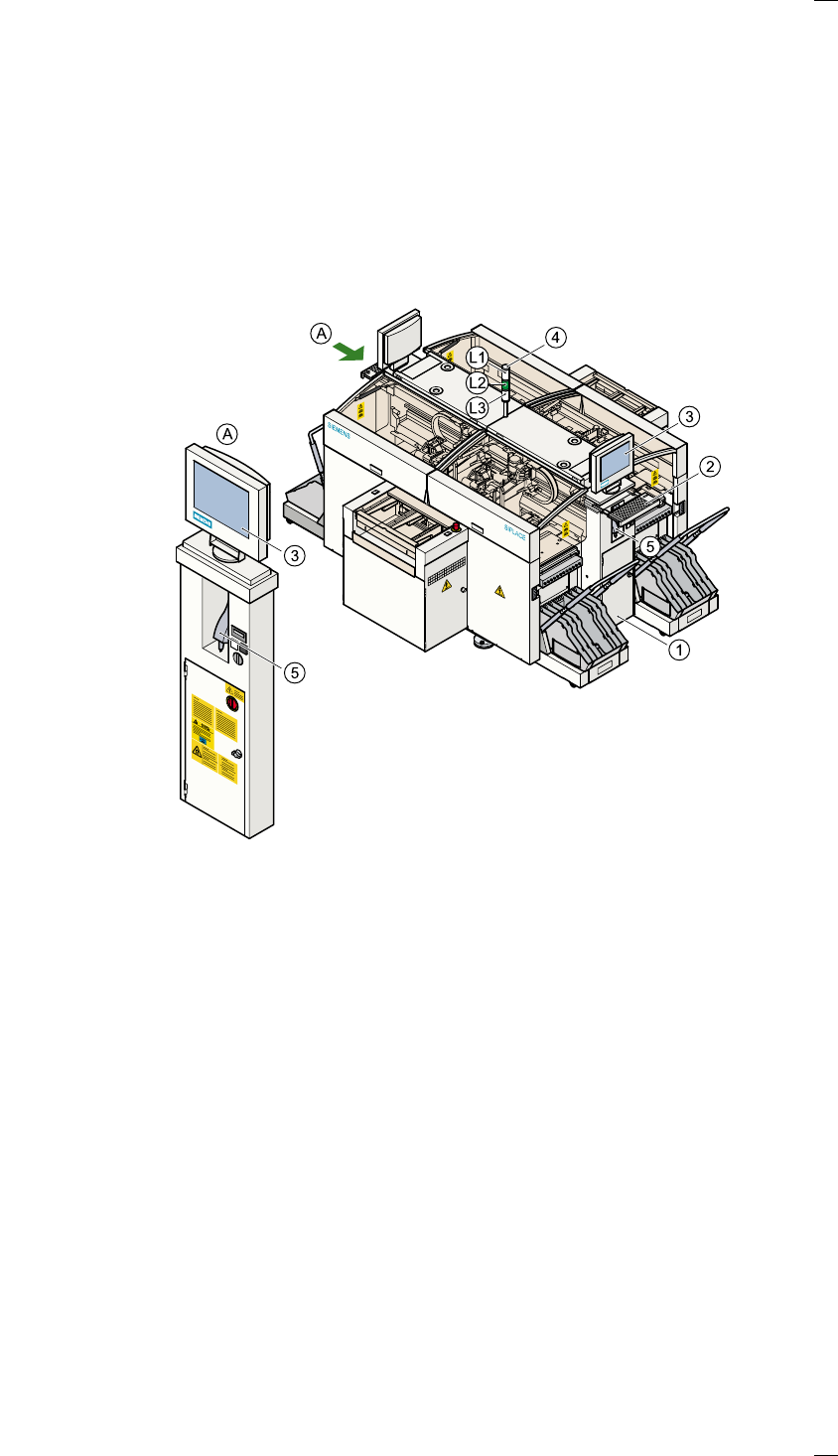
Displays and controls
The following diagram shows the displays and controls.
Description of the displays and controls
All the controls can be reached by anyone who is more than 1.60 m tall.
LCD screen
There is a flat LCD, touch-sensitive screen (touch-screen) on both sides of
the placement system. The resolution is 1024 x 768 pixels.
Keyboard with integral trackball
The keyboard and trackball are located beneath the screen. The keyboard
can be raised and lowered.
a Right operating panel
s Keyboard with integral trackball
d LCD touchscreen
f Main fault indicator
g Component barcode reader
L1 White fault indicator lamp: gantries 1 and 2, locations 1 and 2
L2 Green operating status lamp
L3 White fault indicator lamp: gantries 3 and 4, locations 3 and 4
AView: ’Left side of operating panel’