00192485-02.pdf - 第48页
48 Coupling the compon ent changeover table WARNING Check that the place ment head is outside the r ange of the c omponen t changeove r table. CAUTIO N When coup ling the com ponent chang eover table, m ake sure that the…
47
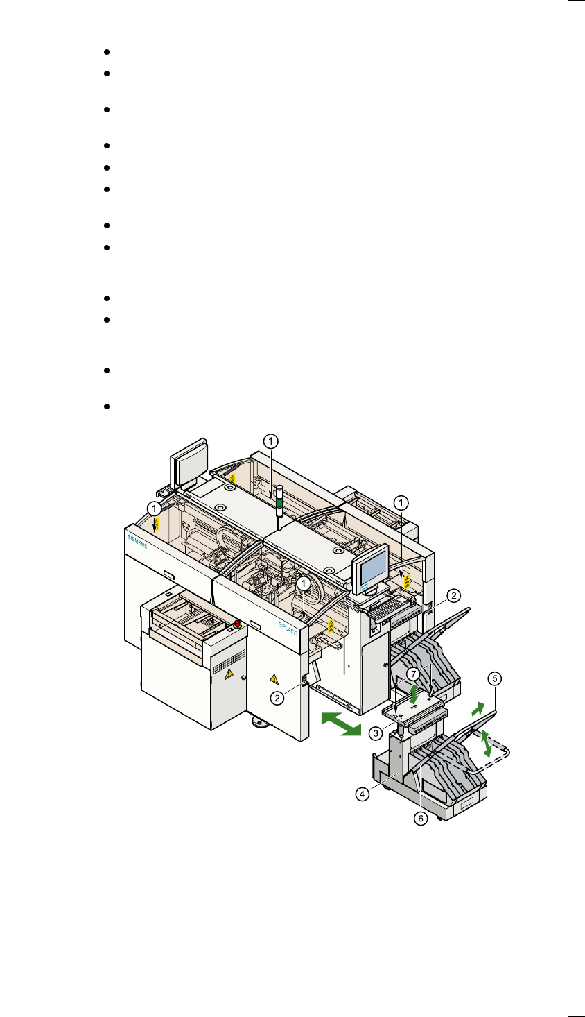
Uncoupling the component changeover table
From the MAIN VIEW menu, click on the STOP PROCESSING icon.
The PCB in progress will be completed. The icons of the SINGLE FUNC-
TIONS menus will then be activated.
Click on the SINGLE FUNCTIONS GANTRY X icon for the gantry you
wish to use (gantry 1, 2, 3 or 4).
Click on the GANTRY FUNCTIONS icon.
From this menu, click on the APPROACH SET-UP POSITION button.
The selected placement head will move over the PCB conveyor so that it
cannot be damaged when the component changeover table is changed.
Lift up the protective cover on the selected gantry.
Pull the two actuating tubes (item 6) towards you and, at the same time,
raise the locking bar (item 5). This will lock the raised component
changeover table plate in its top end position.
Press the button to open the cover flap (item 1).
Press the button (item 1) to raise the component changeover table plate
(item 3) until the component changeover table plate reaches its top end
position.
Unplug (item 2) the component changeover table from the placement sys-
tem.
Pull out the component changeover table.
a Button for raising and lowering the component changeover table plate
beneath the cover flap
s Plug for connecting the component changeover table cable
d component changeover table plate, can be raised and lowered
f component changeover table
g Locking bar
h Actuating tube
j Centering holes for the centering pins
48
Coupling the component changeover table
WARNING
Check that the placement head is outside the range of the component
changeover table.
CAUTION
When coupling the component changeover table, make sure that the com-
ponent changeover table plate is in its top end position and the locking bar
(item 5) is raised.
Check that the contact surface for the component changeover table plate
is clean.
Open the cover flap over the push-button for raising the component
changeover table.
Carefully push the component changeover table into the placement sys-
tem.
Plug the component changeover table connecting cable into the socket
(item 2) on the placement system.
Pull the two actuating tubes (item 6) towards you and, at the same time,
lower the locking bar (item 5) on the component changeover table so that
you can lower the component changeover table plate.
Check that the centering holes on the component changeover table plate
are lined up exactly over the centering pins on the placement system.
Press the button (item 1) until the component changeover table plate
reaches its top end position.
Release the button. The component changeover table plate will descend.
Make sure that the centering pins engage in the centering holes in the
component changeover table plate and that the component changeover
table plate has descended completely.
Raise the component changeover table locking bar (item 5).
Close the cover flap over the push-button (item 1).
Close the protective cover.

49
Index
Symbols
#E
. . . . . . . . . . . . . . . . . . . . . . . . . . . . . . 5, 30
Numerics
12-segment Collect&Place head
. . . . . . . . . 5
A
Abbreviations
. . . . . . . . . . . . . . . . . . . . . . . . 5
Abort processing PCB
. . . . . . . . . . . . . . . . 17
Activate clamping
. . . . . . . . . . . . . . . . . . . . 40
Activate stopper
. . . . . . . . . . . . . . . . . . . . . 40
Actuate dp axis
. . . . . . . . . . . . . . . . . . . . . . 35
Areas of SIPLACE placement stations
. . . . 10
B
Barcode comparison
. . . . . . . . . . . . . . . . . 27
BC
. . . . . . . . . . . . . . . . . . . . . . . . . . . . . . . . 5
BE
. . . . . . . . . . . . . . . . . . . . . . . . . . . . . . . . . 5
Buttons or icons
. . . . . . . . . . . . . . . . . . . . . 24
C
Ca-BC
. . . . . . . . . . . . . . . . . . . . . . . . . . . . . 26
Cmp
. . . . . . . . . . . . . . . . . . . . . . . . . . . . . . . 5
CmpName
. . . . . . . . . . . . . . . . . . . . . . . . . 26
CO
. . . . . . . . . . . . . . . . . . . . . . . . . . . . . . . . 5
Component barcode
. . . . . . . . . . . . . . . . . . 26
Component barcode reader
. . . . . . . . . . . . . 7
Component barcode reader (option)
. . . . . . 8
Component counter
. . . . . . . . . . . . . . . . . 6, 7
Component name
. . . . . . . . . . . . . . . . . . . . 30
Confirm all
. . . . . . . . . . . . . . . . . . . . . . . . . 37
Confirm each change
. . . . . . . . . . . . . . . . . 37
Continue processing
. . . . . . . . . . . . . . . 11, 14
Conveyor belt, high speed
. . . . . . . . . . . . . 40
Coupling the component changeover table
48
Coupling/uncoupling the
component changeover table
. . . . . . . . 46
D
DEV
. . . . . . . . . . . . . . . . . . . . . . . . . . . . 5, 30
Display empty tracks
with component verification
. . . . . . . . . . 32
without component verification
. . . . . . . 32
Display for the machine’s current
operating mode
. . . . . . . . . . . . . . . . . . 15
Displays and controls
. . . . . . . . . . . . . . . . . . 7
description
. . . . . . . . . . . . . . . . . . . . . . . . 7
Division
. . . . . . . . . . . . . . . . . . . . . . . . . . . . 26
E
Emergency stop mushroom-head
push-button
. . . . . . . . . . . . . . . . . . . . . . 6
input side
. . . . . . . . . . . . . . . . . . . . . . . . 11
output side
. . . . . . . . . . . . . . . . . . . . . . . 11
Emergency-stop mushroom-head
push-button
. . . . . . . . . . . . . . . . . . . 6, 11
Enter Password
. . . . . . . . . . . . . . . . . . . . . 21
Error counter
. . . . . . . . . . . . . . . . . . . . . . . .30
Error information, line
. . . . . . . . . . . . . . . . .14
Error number
. . . . . . . . . . . . . . . . . . . . . . . .30
F
Fault list with title bar
. . . . . . . . . . . . . . . . . .30
Fiducial errors
. . . . . . . . . . . . . . . . . . . . . . .45
Flowchart
„Switching on the SIPLACE line“
. . . . .53
Forced air on/off
. . . . . . . . . . . . . . . . . . . . .35
Front panel
. . . . . . . . . . . . . . . . . . . . . . . . .11
G
Gantry reference run
. . . . . . . . . . . . . . . . . .34
GEM status display
. . . . . . . . . . . . . . . . . . .15
General errors
. . . . . . . . . . . . . . . . . . . . . . .30
General operating statuses
. . . . . . . . . . . . . .8
GF
. . . . . . . . . . . . . . . . . . . . . . . . . . . . . . . . .5
GF no.
. . . . . . . . . . . . . . . . . . . . . . . . . . . . .26
Go to service position
. . . . . . . . . . . . . . . . .34
Go to set-up position
. . . . . . . . . . . . . . . . . .34
Go to waiting pos’n
. . . . . . . . . . . . . . . . . . .34
Go to zero pulse
. . . . . . . . . . . . . . . . . . . . .34
Green operating status lamp
. . . . . . . . . . . . .7
Guard
. . . . . . . . . . . . . . . . . . . . . . . . . . . . .11
H
Head reference run
. . . . . . . . . . . . . . . . . . .35
Holding circuit
. . . . . . . . . . . . . . . . . . . . . . .35
Hot key
. . . . . . . . . . . . . . . . . . . . . . . . . . . .12
I
IC
. . . . . . . . . . . . . . . . . . . . . . . . . . . . . . . . . .5
Icon
General errors menu
. . . . . . . . . . . . . . .30
Machine errors menu
. . . . . . . . . . . . . . .30
Track errors menu
. . . . . . . . . . . . . . . . .30
Transport errors menu
. . . . . . . . . . . . . .30
Icons
. . . . . . . . . . . . . . . . . . . . . . . . . . . . . .24
meaning of the
. . . . . . . . . . . . . . . . . . . .14
Input box
. . . . . . . . . . . . . . . . . . . . . . . . . . .19
Input conveyor
. . . . . . . . . . . . . . . . . . . . . . .10
Intermediate conveyor
. . . . . . . . . . . . . . . . .10
K
Key switch
. . . . . . . . . . . . . . . . . . . . . . . . . . .6
Keyboard with integral trackball
. . . . . . . . . .7
Keyboard with integrated mouse
. . . . . . . . .12
L
LCD screen
. . . . . . . . . . . . . . . . . . . . . . . . . .7
LCD touchscreen
. . . . . . . . . . . . . . . . . . . . . .7
Level
. . . . . . . . . . . . . . . . . . . . . . . . . . . . . .26
Line computer
shutdown
. . . . . . . . . . . . . . . . . . . . . . . .22
switching off
. . . . . . . . . . . . . . . . . . . . . .22
List field
. . . . . . . . . . . . . . . . . . . . . . . . . . . .37
Location
. . . . . . . . . . . . . . . . . . . . . . . . . . . .30