00192485-02.pdf - 第47页
47 Uncoupling the com ponent chan geover table From the M AIN VIEW menu, click o n the STOP PR OCESSING i con. The PCB in progress will be comple ted. The icons of the S INGLE FUNC - TIONS men us will the n be activate d…
46
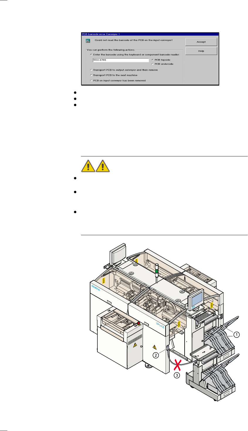
PCB barcode error (option)
If it was not possible to read the barcode properly, the following selection
and dialog box will be displayed on the screen.
enter the correct barcode using the keyboard,
transport the PCB or
remove the PCB from the input conveyor.
Continue processing With this function you can continue processing.
Coupling/uncoupling the component changeover table
Safety instructions for coupling and uncoupling the component
changeover tables
WARNING
NEVER reach into the gap between the component changeover tables
and the placement system frame (item 1) while the machine is running.
The component changeover table must be coupled to the placement sys-
tem whenever the power cable for the component changeover tables is
plugged into or removed from the placement system socket (item 2).
NEVER plug the component changeover table connecting cable into the
placement system socket and then operate the component changeover
table from outside the placement system via the compressed air controls
(item 3).
47
Uncoupling the component changeover table
From the MAIN VIEW menu, click on the STOP PROCESSING icon.
The PCB in progress will be completed. The icons of the SINGLE FUNC-
TIONS menus will then be activated.
Click on the SINGLE FUNCTIONS GANTRY X icon for the gantry you
wish to use (gantry 1, 2, 3 or 4).
Click on the GANTRY FUNCTIONS icon.
From this menu, click on the APPROACH SET-UP POSITION button.
The selected placement head will move over the PCB conveyor so that it
cannot be damaged when the component changeover table is changed.
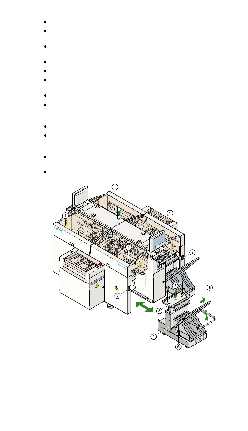
Lift up the protective cover on the selected gantry.
Pull the two actuating tubes (item 6) towards you and, at the same time,
raise the locking bar (item 5). This will lock the raised component
changeover table plate in its top end position.
Press the button to open the cover flap (item 1).
Press the button (item 1) to raise the component changeover table plate
(item 3) until the component changeover table plate reaches its top end
position.
Unplug (item 2) the component changeover table from the placement sys-
tem.
Pull out the component changeover table.
a Button for raising and lowering the component changeover table plate
beneath the cover flap
s Plug for connecting the component changeover table cable
d component changeover table plate, can be raised and lowered
f component changeover table
g Locking bar
h Actuating tube
j Centering holes for the centering pins
48
Coupling the component changeover table
WARNING
Check that the placement head is outside the range of the component
changeover table.
CAUTION
When coupling the component changeover table, make sure that the com-
ponent changeover table plate is in its top end position and the locking bar
(item 5) is raised.
Check that the contact surface for the component changeover table plate
is clean.
Open the cover flap over the push-button for raising the component
changeover table.
Carefully push the component changeover table into the placement sys-
tem.
Plug the component changeover table connecting cable into the socket
(item 2) on the placement system.
Pull the two actuating tubes (item 6) towards you and, at the same time,
lower the locking bar (item 5) on the component changeover table so that
you can lower the component changeover table plate.
Check that the centering holes on the component changeover table plate
are lined up exactly over the centering pins on the placement system.
Press the button (item 1) until the component changeover table plate
reaches its top end position.
Release the button. The component changeover table plate will descend.
Make sure that the centering pins engage in the centering holes in the
component changeover table plate and that the component changeover
table plate has descended completely.
Raise the component changeover table locking bar (item 5).
Close the cover flap over the push-button (item 1).
Close the protective cover.