00192485-02.pdf - 第41页
41 Click on OK in the di alog box to en d the op eration. Update Click on this button t o check wheth er a PCB was removed PCB status during transpo rtation. If a PCB was rem oved, it is cleared from th e display and the…
40
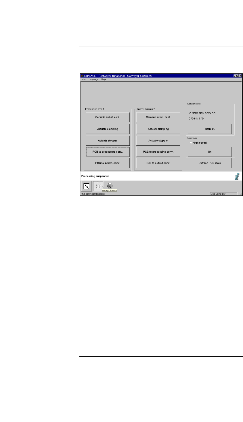
’Single functions PCB transport 1’ menu
This menu is used for checking and setting the function modules of the
PCB conveyor. If the twin conveyor option is installed, the Single functions
PCB transport 2 menu will be activated. The same functions as with PCB
transport 1 will then be available to you.
NOTE
To move the gantries, close the covers and then press the start button. All
gantry and head axes will move at low speed.
Buttons in the ‘Processing area 1’ and ‘Processing area 2’ boxes
The next three menu options act in the same way as a toggle switch.
The following menu options act in the same way as a switch (ON/OFF)
when they are clicked.
Ceramic substrate Click on the ’Ceramic substrate centering’ button to activate or
centering (option) deactivate clamping in order to center the substrate.
Activate clamping Click on the ’Activate clamping’ button to turn clamping on or off.
Activate stopper Click on the ’Activate stopper’ button to move the stopper in or out.
PCB to proc. conv. The PCB is transported from the input conveyor (IC) or intermediate con-
veyor (IC) to processing conveyor 1 (PC1) or processing conveyor 2
(PC2), where it is stopped and clamped in place.
PCB to interm. conv. The PCB is transported from processing conv. 1 (PC1) to the intermediate
conveyor (IC), where it is stopped and clamped in place.
PCB to output conv. The PCB is transported from processing conveyor 2 (PC2) to the output
conveyor (OC).
‘Sensor state’ box
Update sensor This menu option is used to check the statuses of the ultrasonic sensors.
IC/PC1/IC/PC2/OC on the input, placement, intermediate or output conveyor:
1 = has responded
0 = has not responded
‘Conveyor’ box
High Provides the option of setting different transport
speed speeds.
PLEASE NOTE
Make sure that there are no PCBs on the conveyor belts. The input
conveyor belt only runs at high speed.
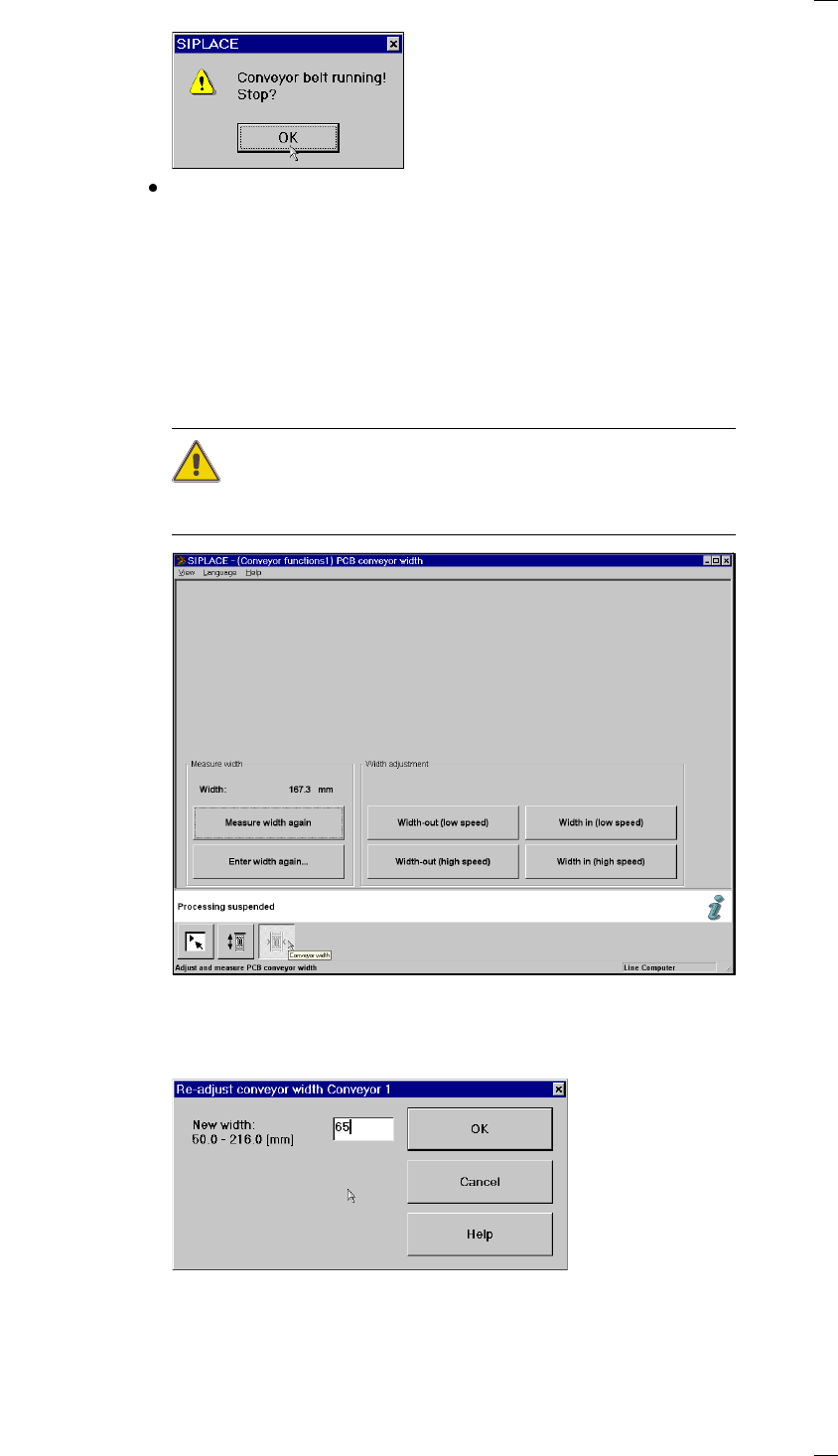
On Starts the conveyor belts. The following dialog box appears.
41
Click on OK in the dialog box to end the operation.
Update Click on this button to check whether a PCB was removed
PCB status during transportation. If a PCB was removed, it is cleared from the display
and the stored data.
’PCB conveyor width’ menu
This menu is used for measuring and adjusting the conveyor belt width.
CAUTION
Make sure there are no boards on the conveyor belts when you adjust the
conveyor belt width.
‘Measure width’ box
Measure width again Used to display, measure and save the width of the PCB conveyor.
Enter width again … Click on this button to open a box for entering the PCB conveyor width.
For the single conveyor, you can enter a width between 50 and 460 mm.
The possible values range from 50 mm to 216 mm for the dual conveyor.

42
‘Set width’ box
This menu option is to set the PCB conveyor width at a higher or lower
speed. If you change the width, then the conveyor width is measured and
updated at the left-hand gantry when you edit the Single functions menu.
Use this menu to display the current width again.
‘Set width’ buttons
Larger (slow) Increases the width of the conveyors in 0.1 mm increments.
Larger (fast) Increases the width of the conveyors in 1 mm increments.
Smaller (slow) Decreases the width of the conveyors in 0.1 mm increments.
Smaller (fast) Decreases the width of the conveyors in 1 mm increments.