00192485-02.pdf - 第16页
16 T r oubleshootin g status display ( icon ; ) Click on thi s icon on ce you have c orrected the fault. The current error i n the status box f or display ing error mes sages (icon g ) is cleared. T he entry is retained …
15
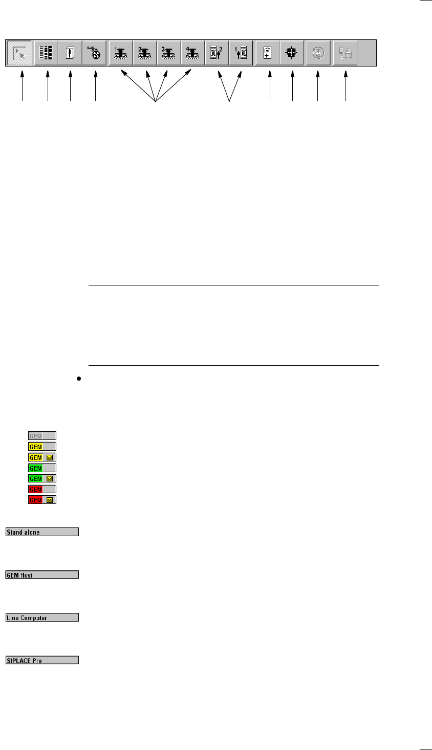
Toolbar with icons of submenus (icon h)
NOTES to points 6 and 10
The single functions for Conveyor 2 can only be called if a twin conveyor
has been configured.
The GEM interface functions cannot be called unless this has been config-
ured.
The "GEM Interface" option cannot be configured in the current software
version.
Click the required button in the toolbar.
The user interface is switched to the corresponding view.
The button corresponding to the view which is currently active itself
becomes inactive.
GEM status display (option) (icon
k)
GEM not initialized
GEM establishing SECS connection, no message from host
GEM establishing SECS connection, message from host
SECS connection online, no message from host
SECS connection online, message from host
SECS connection offline, no message from host
SECS connection offline, message from host
Display for the machine’s current operating mode (icon
l)
Stand alone
The station computer is not connected to an external computer.
Placement programs are loaded from the local hard disk.
GEM Host
The station computer is connected to a host computer. The placement
programs are downloaded from the host computer.
Line Computer
The station computer is connected to the line computer. The placement
programs are downloaded from the line computer.
SIPLACE Pro
In this operating mode, a connection is established with the SIPLACE Pro
programming system.
a Main view
s Set-up, placement functions
d Error, placement functions
f Component feeder, placement functions
g Gantry 1 to 4, single functions
h PCB conveyors 1 and 2 (option), single functions
j Teach fiducials, vision functions
(’Line engineer’ access level or higher only)
k Test component, vision functions
(’Line engineer’ access level or higher only)
l Start SITEST test program (↑ SITEST)
(’Service engineer’ access level or higher only)
; GEM interface (option)
1 8 9 10765432
16
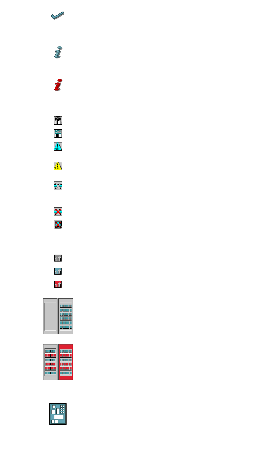
Troubleshooting status display (icon ;)
Click on this icon once you have corrected the fault. The current error in
the status box for displaying error messages
(icon
g) is cleared. The entry is retained in the error lists.
Information and help system (icon A)
Starts the context-sensitive help system for the current view. This contains
brief descriptions of all the controls on screen.
Information and help system (icon
A)
Starts the help system and displays the possible causes of the current
error, together with tips on how to correct it.
Angle for component / PCB barcode … (icon
D)
Barcode-aided replenishment of components is active
The PCB barcode is active.
Machine options were modified (’Line engineer’ access level or higher
only)
Software options were modified (’Service engineer’ access level or higher
only)
The automatic compressed air cut-out is active (’Line engineer’ access
level or higher only). The compressed air supply is disconnected if the
machine has stopped for a predefined period.
The compressed air is switched off.
The connection to the line computer is interrupted. No data can be
received.
Status display for the transport signal interface (icon J)
Grayed out while the machine starts up
Green when the transport signal interface is enabled
Red when the transport signal interface is disabled.
Status display for the locations (icon
K)
a = No set-up at the corresponding location
s = Set-up present
d = Set-up present – at least one "Track empty" error
f = Machine stopped due to several track errors
Status display for the PCBs (icon
L)
PCB being processed
The PCB has been taken into the system and is being processed. The
PCB icon is displayed in blue-green.
as
df
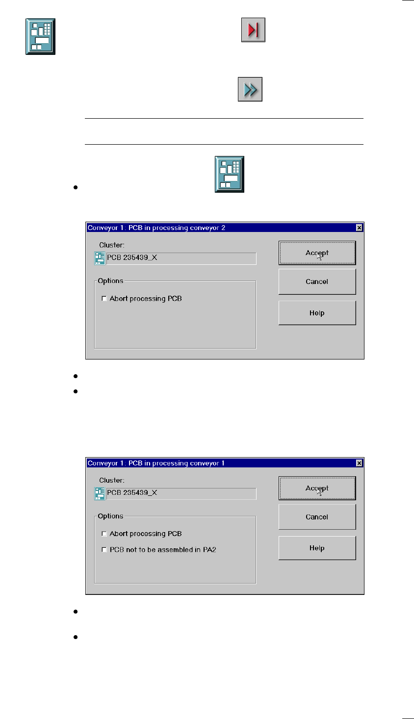
17
Processing of PCB stopped
If processing is interrupted by clicking on
"Stop processing PCB",
by a machine stoppage or by pressing the Stop button, the PCB icon
appears in blue-green with contoured edges.
You can continue processing by clicking
or abort it by clicking the PCB icon.
NOTE
The procedure used to abort processing is described below.
Abort processing PCB
Click the corresponding PCB icon .
If the PCB is located on processing conveyor 2, the following dialog box is
opened.
Click the checkbox "Abort processing PCB".
Click the Accept button.
Processing of the PCB is aborted.
The incompletely assembled PCB is transported to the output conveyor
and the operator is requested to remove it by hand.
If the PCB is located on processing conveyor 1, the following dialog box is
opened.
Check the box "Abort processing PCB" if the PCB is to be transported to
the output conveyor without further processing.
Check the box "PCB not to be assembled in PC2" if the PCB is to be pro-
cessed on processing conveyor 1 and is then to be transported to the out-
put conveyor without being processed on processing conveyor 2.