00192485-02.pdf - 第36页
36 ’ V acuum test revolver hea d ’ menu When this function i s executed th e revolve r head perform s a head refer- ence run. At the same time the vacuum values of all nozzles at the pick-up position are me asured wit h …
35
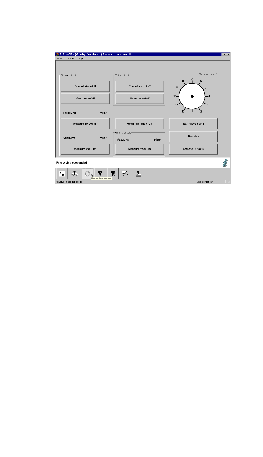
’Revolver head functions’ menu
NOTE
If you wish to carry out revolver head functions with the cover open, this
will only be possible with the key-operated switch in position "I".
Star in position 1 The star and the Z-axis of the revolver head carry out a reference run. At
the same time the segment at the star position is rotated into the pick-up /
placement position.
Star step The star is cycled onward by one position each time and its position dis-
played graphically in the window.
Actuate DP axis The nozzle of the segment at the dp1 turning station is rotated by 90°.
Head reference run The head axes carry out a reference run. During this, components are
ejected into the rejects container.
Pick-up circuit Forced air on/off The forced air is switched on or off
at the pick-up position.
Vacuum on/off The vacuum is switched on or off
at the pick-up position.
Measure forced air The pressure of the forced air is measured
at the pick-up position and the measured
value displayed in mbar.
Measure vacuum The vacuum value is measured for the
nozzle at the pick-up position and the
measured value displayed in mbar.
Reject circuit Forced air on/off The forced air is switched on or off
at the reject position.
Vacuum on/off The vacuum is switched on or off
at the reject position.
Holding circuit Measure vacuum The vacuum of the holding circuit is
measured and the measured value
displayed in mbar.
36
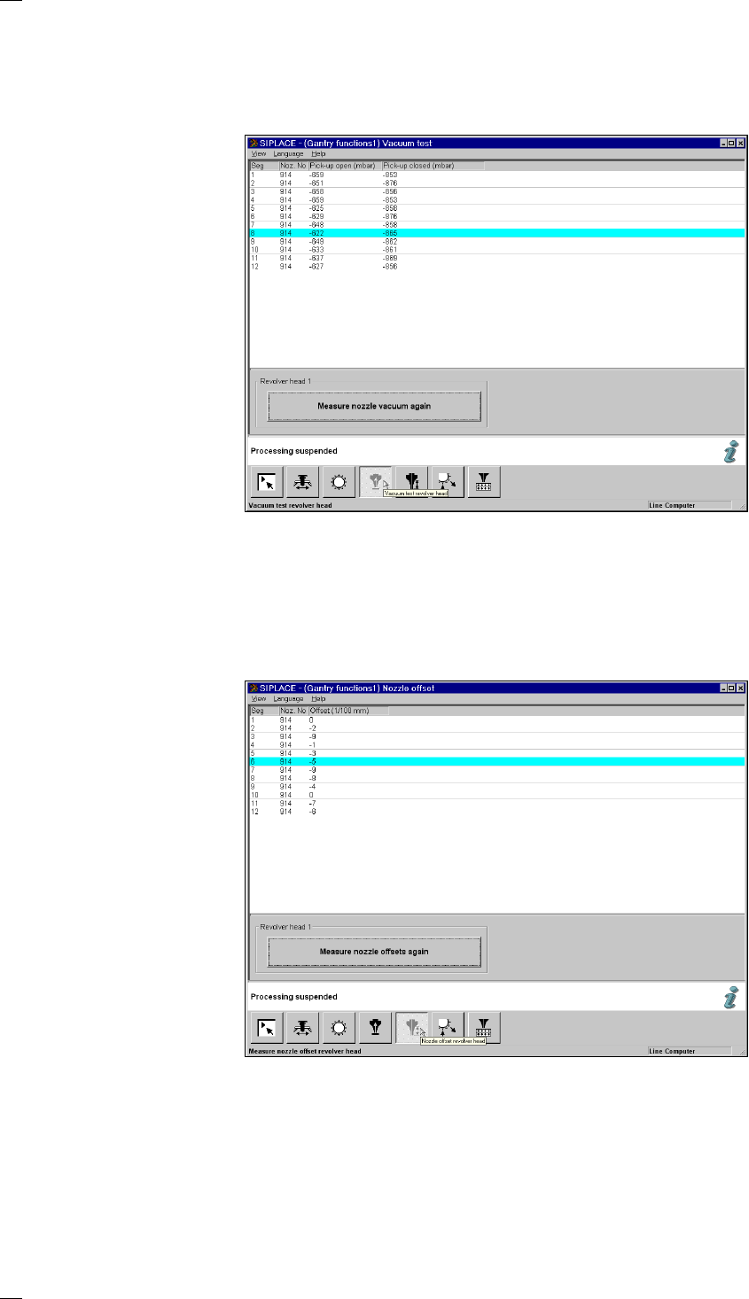
’Vacuum test revolver head’ menu
When this function is executed the revolver head performs a head refer-
ence run. At the same time the vacuum values of all nozzles at the pick-up
position are measured with the nozzles both closed and open. The values
are then displayed in the list.
’Nozzle offset revolver head’ menu
When this function is executed you will be asked to press the start button
by a screen message. The gantry will then travel over a measurement
position on the board conveyor. Here the Z-heights of all segments are
measured and displayed on the screen. The gantry then returns to its ini-
tial waiting position.
37
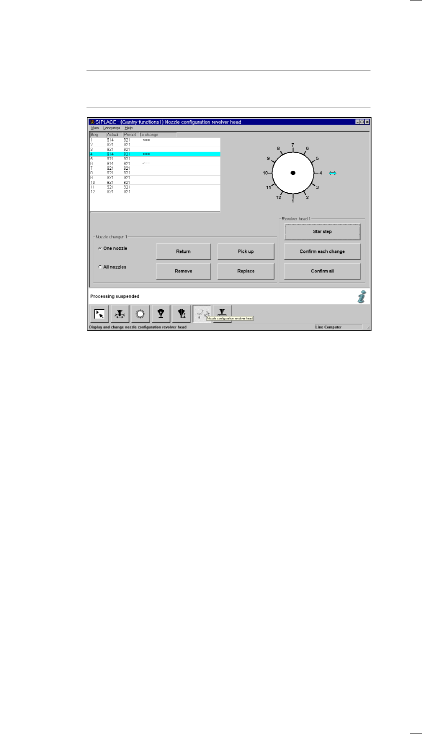
’Nozzle configuration revolver head’ menu
Within the Nozzle configuration revolver head menu you can view the noz-
zle configuration and check nozzles. If a nozzle changer has been
installed you can change the nozzles with the aid of this menu.
NOTE
Nozzle-changing is only possible with the prespecified cluster and pre-
specified setup.
List field
The nozzle configuration is displayed with the programmed and actual val-
ues. Nozzles marked with an arrow in the ’To change’ column have to be
changed. The cyan bar indicates that the corresponding nozzle is in the
changing position.
Revolv. head diagram The arrow shows the changing position for the nozzle in question.
‘Revolver head’ box
Star step The star is cycled onward by one position whenever you click on this
button.
Confirm each
change To do this, carry out the following steps.
– Step the nozzle indicated by an arrow into the changeover position.
– Exchange the nozzle.
– Click on the ‘Confirm single change’ button. The desired and actual values
in the list box must tally.
Confirm all If you have exchanged several nozzles that were indicated by an arrow,
you can use a single command at the end to confirm all the changes.
Click on the ‘Confirm all’ button. The desired and actual values for all
nozzles in the list box must tally.
‘Nozzle changer’ box
One nozzle When ’One nozzle’ is activated, the ’Return’, ’Pick up’, ’Remove’ and
’Replace’ functions will only be carried out for the selected nozzle. If you
click on one of these functions, an input box will appear so that you can
enter the segment number. The default value that appears in the input box
is the number of the segment currently at the change position. It is indi-
cated by cyan-colored arrow.