00192485-02.pdf - 第4页
4 Troubleshoo ting . . . . . . . . . . . . . . . . . . . . . . . . . . . . . . . . . . . . . . . . . . . . . . . . . . . . . . . . . . . 43 Track errors . . . . . . . . . . . . . . . . . . . . . . . . . . . . . . . . . .…

3
Contents
Contents . . . . . . . . . . . . . . . . . . . . . . . . . . . . . . . . . . . . . . . . . . . . . . . . . . . . . . . . . . . . . . . . . .3
Abbreviations. . . . . . . . . . . . . . . . . . . . . . . . . . . . . . . . . . . . . . . . . . . . . . . . . . . . . . . . . . . . . . .5
Structure of the placement system . . . . . . . . . . . . . . . . . . . . . . . . . . . . . . . . . . . . . . . . . . . . . .5
Switches and buttons on the placement system . . . . . . . . . . . . . . . . . . . . . . . . . . . . . . . . . . . .5
Main switch. . . . . . . . . . . . . . . . . . . . . . . . . . . . . . . . . . . . . . . . . . . . . . . . . . . . . . . . . . . . . .6
Key switch . . . . . . . . . . . . . . . . . . . . . . . . . . . . . . . . . . . . . . . . . . . . . . . . . . . . . . . . . . . . . .6
Stop button. . . . . . . . . . . . . . . . . . . . . . . . . . . . . . . . . . . . . . . . . . . . . . . . . . . . . . . . . . . . . .6
Start button. . . . . . . . . . . . . . . . . . . . . . . . . . . . . . . . . . . . . . . . . . . . . . . . . . . . . . . . . . . . . .6
Emergency stop mushroom-head push-button . . . . . . . . . . . . . . . . . . . . . . . . . . . . . . . . . .6
Component counter . . . . . . . . . . . . . . . . . . . . . . . . . . . . . . . . . . . . . . . . . . . . . . . . . . . . . . .7
Displays and controls . . . . . . . . . . . . . . . . . . . . . . . . . . . . . . . . . . . . . . . . . . . . . . . . . . . . . . . .7
Description of the displays and controls. . . . . . . . . . . . . . . . . . . . . . . . . . . . . . . . . . . . . . . .7
LCD screen . . . . . . . . . . . . . . . . . . . . . . . . . . . . . . . . . . . . . . . . . . . . . . . . . . . . . . . . . . . . .7
Keyboard with integral trackball . . . . . . . . . . . . . . . . . . . . . . . . . . . . . . . . . . . . . . . . . . . . . .7
Component barcode reader (option) . . . . . . . . . . . . . . . . . . . . . . . . . . . . . . . . . . . . . . . . . .8
Main fault indicator . . . . . . . . . . . . . . . . . . . . . . . . . . . . . . . . . . . . . . . . . . . . . . . . . . . . . . . .8
Functional description of the main fault indicator. . . . . . . . . . . . . . . . . . . . . . . . . . . . . . . . .8
General operating statuses . . . . . . . . . . . . . . . . . . . . . . . . . . . . . . . . . . . . . . . . . . . . . . . . .8
Programmed operating status displays . . . . . . . . . . . . . . . . . . . . . . . . . . . . . . . . . . . . . . . .8
Machine Areas . . . . . . . . . . . . . . . . . . . . . . . . . . . . . . . . . . . . . . . . . . . . . . . . . . . . . . . . . .10
Safety devices. . . . . . . . . . . . . . . . . . . . . . . . . . . . . . . . . . . . . . . . . . . . . . . . . . . . . . . . . . . . .11
Emergency stop mushroom-head push-buttons . . . . . . . . . . . . . . . . . . . . . . . . . . . . . . . .11
Protective covers . . . . . . . . . . . . . . . . . . . . . . . . . . . . . . . . . . . . . . . . . . . . . . . . . . . . . . . .11
Menu control of the machine. . . . . . . . . . . . . . . . . . . . . . . . . . . . . . . . . . . . . . . . . . . . . . . . . .12
Keyboard with integrated mouse (trackball). . . . . . . . . . . . . . . . . . . . . . . . . . . . . . . . . . . .12
Touchscreen. . . . . . . . . . . . . . . . . . . . . . . . . . . . . . . . . . . . . . . . . . . . . . . . . . . . . . . . . . . .12
User interface . . . . . . . . . . . . . . . . . . . . . . . . . . . . . . . . . . . . . . . . . . . . . . . . . . . . . . . . . . . . .13
Main view – arrangement and explanation of the icons . . . . . . . . . . . . . . . . . . . . . . . . . . .13
Meaning of the icons . . . . . . . . . . . . . . . . . . . . . . . . . . . . . . . . . . . . . . . . . . . . . . . . . . . . .14
On-screen displays - warning and message boxes . . . . . . . . . . . . . . . . . . . . . . . . . . . . . .19
On-screen displays - input box. . . . . . . . . . . . . . . . . . . . . . . . . . . . . . . . . . . . . . . . . . . . . .19
On-screen display - control box . . . . . . . . . . . . . . . . . . . . . . . . . . . . . . . . . . . . . . . . . . . . .20
On-screen display - selection box . . . . . . . . . . . . . . . . . . . . . . . . . . . . . . . . . . . . . . . . . . .20
Switching on the SIPLACE line . . . . . . . . . . . . . . . . . . . . . . . . . . . . . . . . . . . . . . . . . . . . . . . .21
Switching on the line computer . . . . . . . . . . . . . . . . . . . . . . . . . . . . . . . . . . . . . . . . . . . . .21
Starting the stations . . . . . . . . . . . . . . . . . . . . . . . . . . . . . . . . . . . . . . . . . . . . . . . . . . . . . .21
Switching off the SIPLACE line . . . . . . . . . . . . . . . . . . . . . . . . . . . . . . . . . . . . . . . . . . . . . . .22
Switching off the line computers . . . . . . . . . . . . . . . . . . . . . . . . . . . . . . . . . . . . . . . . . . . .22
Switching off the stations . . . . . . . . . . . . . . . . . . . . . . . . . . . . . . . . . . . . . . . . . . . . . . . . . .23
Operator Guidance . . . . . . . . . . . . . . . . . . . . . . . . . . . . . . . . . . . . . . . . . . . . . . . . . . . . . . . . .24
’Main view’ menu (user level: ’operator’) . . . . . . . . . . . . . . . . . . . . . . . . . . . . . . . . . . . . . .24
’Machine options’ menu . . . . . . . . . . . . . . . . . . . . . . . . . . . . . . . . . . . . . . . . . . . . . . . . . . .25
‘Set-up’ menu . . . . . . . . . . . . . . . . . . . . . . . . . . . . . . . . . . . . . . . . . . . . . . . . . . . . . . . . . . .26
’Component verification with barcode’ menu . . . . . . . . . . . . . . . . . . . . . . . . . . . . . . . . . . .27
‘Set-up check for entire location’ menu . . . . . . . . . . . . . . . . . . . . . . . . . . . . . . . . . . . . . . .28
‘Table functions’ menu . . . . . . . . . . . . . . . . . . . . . . . . . . . . . . . . . . . . . . . . . . . . . . . . . . . .29
’Display errors’ menu . . . . . . . . . . . . . . . . . . . . . . . . . . . . . . . . . . . . . . . . . . . . . . . . . . . . .30
’Track errors location X’ menu . . . . . . . . . . . . . . . . . . . . . . . . . . . . . . . . . . . . . . . . . . . . . .31
’Feeders’ menu. . . . . . . . . . . . . . . . . . . . . . . . . . . . . . . . . . . . . . . . . . . . . . . . . . . . . . . . . .31
’Display and refill empty tracks’ menu . . . . . . . . . . . . . . . . . . . . . . . . . . . . . . . . . . . . . . . .32
’Display magazines and change inventory levels’ menu . . . . . . . . . . . . . . . . . . . . . . . . . .33
’Display linear feeder and vibrate’ menu . . . . . . . . . . . . . . . . . . . . . . . . . . . . . . . . . . . . . .33
’Single functions - Gantries 1/2/3/4’ menu . . . . . . . . . . . . . . . . . . . . . . . . . . . . . . . . . . . . .33
’Gantry functions’ menu . . . . . . . . . . . . . . . . . . . . . . . . . . . . . . . . . . . . . . . . . . . . . . . . . . .34
’Revolver head functions’ menu . . . . . . . . . . . . . . . . . . . . . . . . . . . . . . . . . . . . . . . . . . . . .35
’Vacuum test revolver head’ menu. . . . . . . . . . . . . . . . . . . . . . . . . . . . . . . . . . . . . . . . . . .36
’Nozzle offset revolver head’ menu . . . . . . . . . . . . . . . . . . . . . . . . . . . . . . . . . . . . . . . . . .36
’Nozzle configuration revolver head’ menu . . . . . . . . . . . . . . . . . . . . . . . . . . . . . . . . . . . .37
‘Revolver head nozzle changer configuration’ menu . . . . . . . . . . . . . . . . . . . . . . . . . . . . .38
’Single functions PCB transport 1’ menu . . . . . . . . . . . . . . . . . . . . . . . . . . . . . . . . . . . . . .40
’PCB conveyor width’ menu . . . . . . . . . . . . . . . . . . . . . . . . . . . . . . . . . . . . . . . . . . . . . . . .41

4
Troubleshooting . . . . . . . . . . . . . . . . . . . . . . . . . . . . . . . . . . . . . . . . . . . . . . . . . . . . . . . . . . . 43
Track errors. . . . . . . . . . . . . . . . . . . . . . . . . . . . . . . . . . . . . . . . . . . . . . . . . . . . . . . . . . . . 43
Machine errors . . . . . . . . . . . . . . . . . . . . . . . . . . . . . . . . . . . . . . . . . . . . . . . . . . . . . . . . . 44
Transport errors . . . . . . . . . . . . . . . . . . . . . . . . . . . . . . . . . . . . . . . . . . . . . . . . . . . . . . . . 44
Fiducial errors . . . . . . . . . . . . . . . . . . . . . . . . . . . . . . . . . . . . . . . . . . . . . . . . . . . . . . . . . . 45
Nozzle configuration errors. . . . . . . . . . . . . . . . . . . . . . . . . . . . . . . . . . . . . . . . . . . . . . . . 45
PCB barcode error (option). . . . . . . . . . . . . . . . . . . . . . . . . . . . . . . . . . . . . . . . . . . . . . . . 46
Coupling/uncoupling the component changeover table . . . . . . . . . . . . . . . . . . . . . . . . . . . . . 46
Safety instructions for coupling and uncoupling the component changeover tables. . . . . 46
Uncoupling the component changeover table. . . . . . . . . . . . . . . . . . . . . . . . . . . . . . . . . . 47
Coupling the component changeover table. . . . . . . . . . . . . . . . . . . . . . . . . . . . . . . . . . . . 48
Index . . . . . . . . . . . . . . . . . . . . . . . . . . . . . . . . . . . . . . . . . . . . . . . . . . . . . . . . . . . . . . . . . . . 49
Flowchart "Switching ON the SIPLACE Line" . . . . . . . . . . . . . . . . . . . . . . . . . . . . . . . . . . . . 53
5
Abbreviations
The following abbreviations are employed in this quick reference guide:
#E Error counter
BC Barcode
BE, Cmp, CO Component
DEV Originator of the error
GF Package form
IC Input conveyor
IC Intermediate conveyor
OC Output conveyor
PC1 Processing conveyor 1
PC2 Processing conveyor 2
PCB, LP Printed circuit board
Seg Segment
SF Single functions
TR/D/T Track/Division/Tray
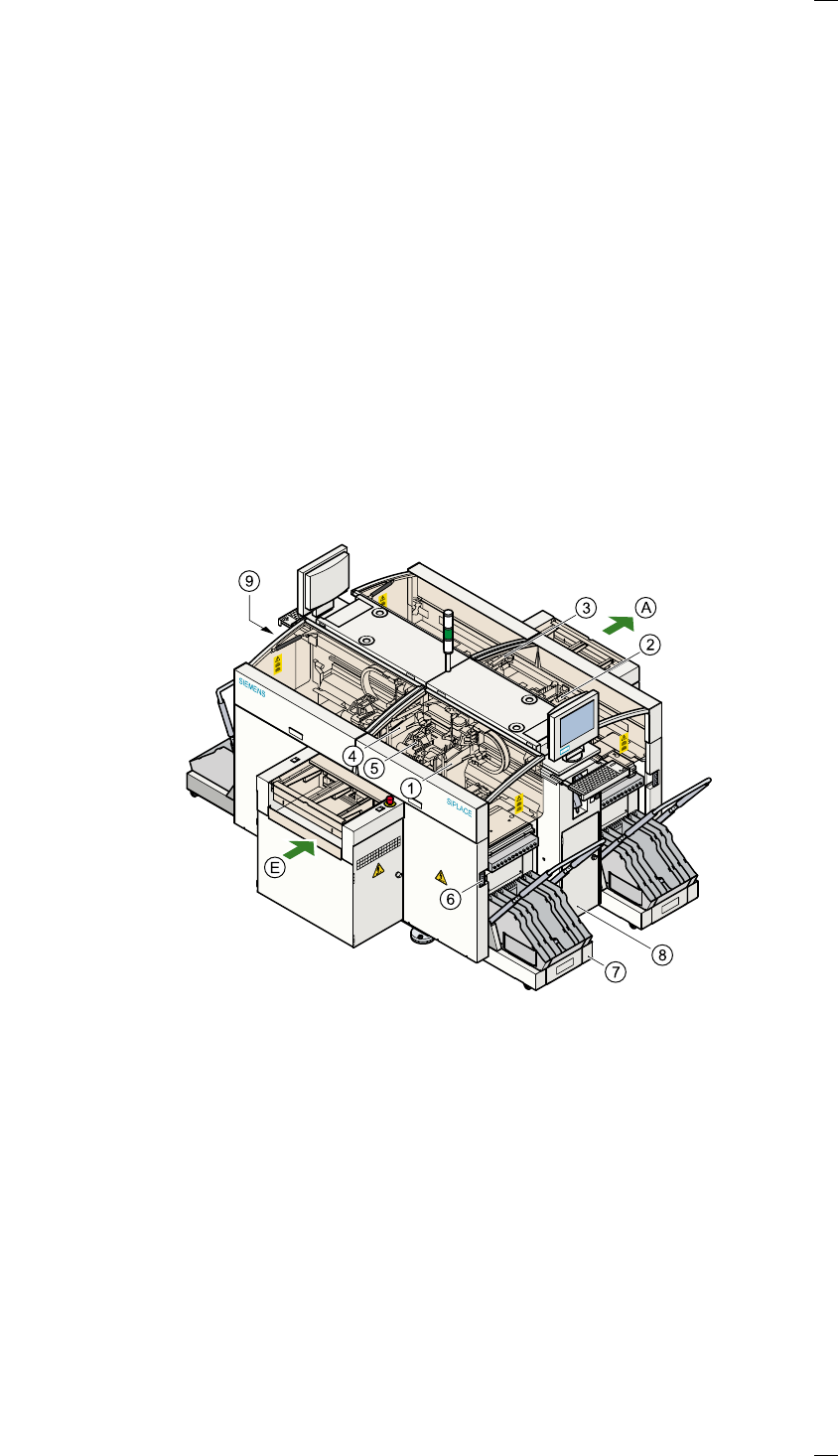
Structure of the placement system
Switches and buttons on the placement system
The following diagram shows the positions of the switches and buttons on
the placement system.
a Gantry 1 j Component changeover table
s Gantry 2 k Controls, right (pneumatic system)
d Gantry 3 l Controls, left (electrical system)
f Gantry 4
g 12-segment Collect&Place head A PCB conveyor - output side
h Socket for the component
changeover table cable
E PCB conveyor - input side