00192485-02.pdf - 第42页
42 ‘ Set wi d th ’ box This menu option is to set the PC B convey or width at a highe r or lower speed. If y ou chang e the width, then the conve yor width is measu red and updated a t the left-hand gantry when you edit …
41
Click on OK in the dialog box to end the operation.
Update Click on this button to check whether a PCB was removed
PCB status during transportation. If a PCB was removed, it is cleared from the display
and the stored data.
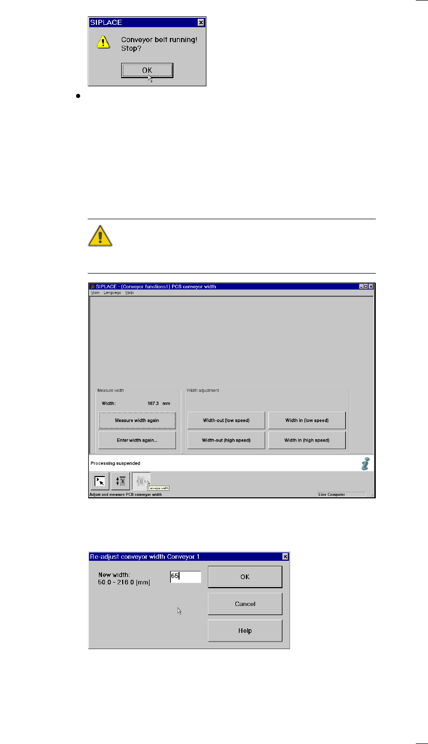
’PCB conveyor width’ menu
This menu is used for measuring and adjusting the conveyor belt width.
CAUTION
Make sure there are no boards on the conveyor belts when you adjust the
conveyor belt width.
‘Measure width’ box
Measure width again Used to display, measure and save the width of the PCB conveyor.
Enter width again … Click on this button to open a box for entering the PCB conveyor width.
For the single conveyor, you can enter a width between 50 and 460 mm.
The possible values range from 50 mm to 216 mm for the dual conveyor.

42
‘Set width’ box
This menu option is to set the PCB conveyor width at a higher or lower
speed. If you change the width, then the conveyor width is measured and
updated at the left-hand gantry when you edit the Single functions menu.
Use this menu to display the current width again.
‘Set width’ buttons
Larger (slow) Increases the width of the conveyors in 0.1 mm increments.
Larger (fast) Increases the width of the conveyors in 1 mm increments.
Smaller (slow) Decreases the width of the conveyors in 0.1 mm increments.
Smaller (fast) Decreases the width of the conveyors in 1 mm increments.
43
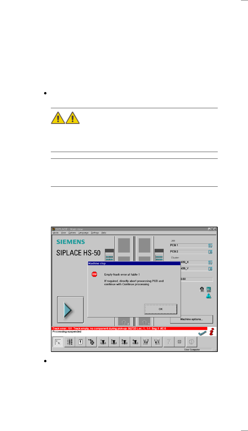
Troubleshooting
If errors occurs at the placement machine, such as
– track errors
– machine errors
– transport errors
– fiducial errors
– nozzle configuration errors or
– PCB bar code reading errors
it will be stopped and the warning box is displayed on the screen with a
message such as ’Track empty error ...’ and so on.
You should comply with the instructions in the warning box and carry out
the actions requested.
WARNING
Only personnel with the corresponding training and qualifications are per-
mitted to carry out actions requiring Line engineer authorization since
improper treatment of the machine may result in serious physical injury
and considerable damage to property.
NOTE
Close the protective covers before attempting to move the axes.
If you wish to carry out head functions with the cover open, this will only be
possible with the key-operated switch in position "I".
Track errors
Placement of a board will continue until there is none left of all of the com-
ponents which are to be inserted. In this situation the machine will stop
and the error message Track empty will appear on the screen.
Click on OK to acknowledge and then select from the functions displayed:
Abort process. PCB Click on the affected PCB, select 'Abort processing PCB' (see the ’Abort
processing PCB’ on page 17).