Micron Technical Reference V9 Volume 1.pdf - 第104页
PRINTER OVERVIEW MODULE OVERVIEWS 4.10 Technical Reference Manual Chapter Issue 11, Jan 17 Underscreen Cleaner The underscreen cleaner module a utomati cally cleans the underside of the stencil so reducing the build up o…
PRINTER OVERVIEW
MODULE OVERVIEWS
Chapter Issue 11, Jan 17 Technical Reference Manual 4.9
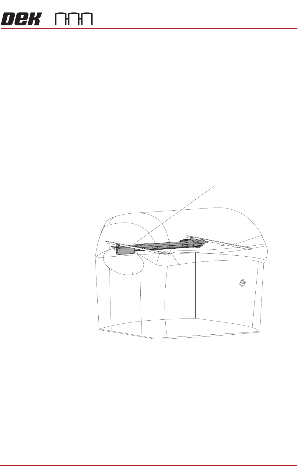
Camera System
Module
The function of the camera system is to supply a visual indication of stencil to
board alignment and board/stencil inspection data to the printer PC enclosure.
The captured information supplied to the PC enclosure enables the processor
to:
• Align the stencil to the product board
• Provide visual information for the user on the MMI monitor
The camera assembly traverses horizontally in the X and Y axis and is driven
by either:
• Rotary Servo Motors
• Linear Servo Motors
The camera carriage is also used to transport the board stop and the under-
screen cleaner.
Figure 4-12 Camera System
Camera System
PRINTER OVERVIEW
MODULE OVERVIEWS
4.10 Technical Reference Manual Chapter Issue 11, Jan 17
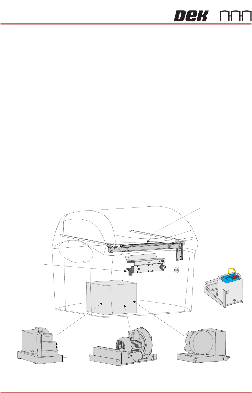
Underscreen
Cleaner
The underscreen cleaner module automatically cleans the underside of the
stencil so reducing the build up of paste.The underscreen cleaner is driven
across the underside of the stencil by the camera carriage.
There are two types of underscreen cleaner available:
• Underscreen Cleaner
• Cyclone Underscreen Cleaner
The underscreen cleaner module provides the facility to store solvent for wet
cleaning cycles. The external solvent tank may be mounted on either side or the
rear of the printer and is secured to the printer frame.
NOTE
Type 4 Printers The external solvent tank may be mounted on either side of the
printer and is secured to the printer frame.
The vacuum filtration unit removes excess paste from the stencil and solvent/
print material fumes. There are four types of vacuum filtration units:
• VF35i Vacuum Filtration Unit
• VF30 Vacuum Filtration Unit (Type 5 printers only)
• VF25 Vacuum Filtration Unit
• VF10 Venturi Vacuum Filtration Unit
Figure 4-13 Underscreen Cleaner Components
Underscreen Cleaner
External Solvent
Tank
VF35i Vacuum Filtration Unit
VF25 Vacuum Filtration Unit
VF10 Venturi
Vacuum Filtration
Unit
V Vacuum Filtration UnitF30
PRINTER OVERVIEW
MODULE OVERVIEWS
Chapter Issue 11, Jan 17 Technical Reference Manual 4.11
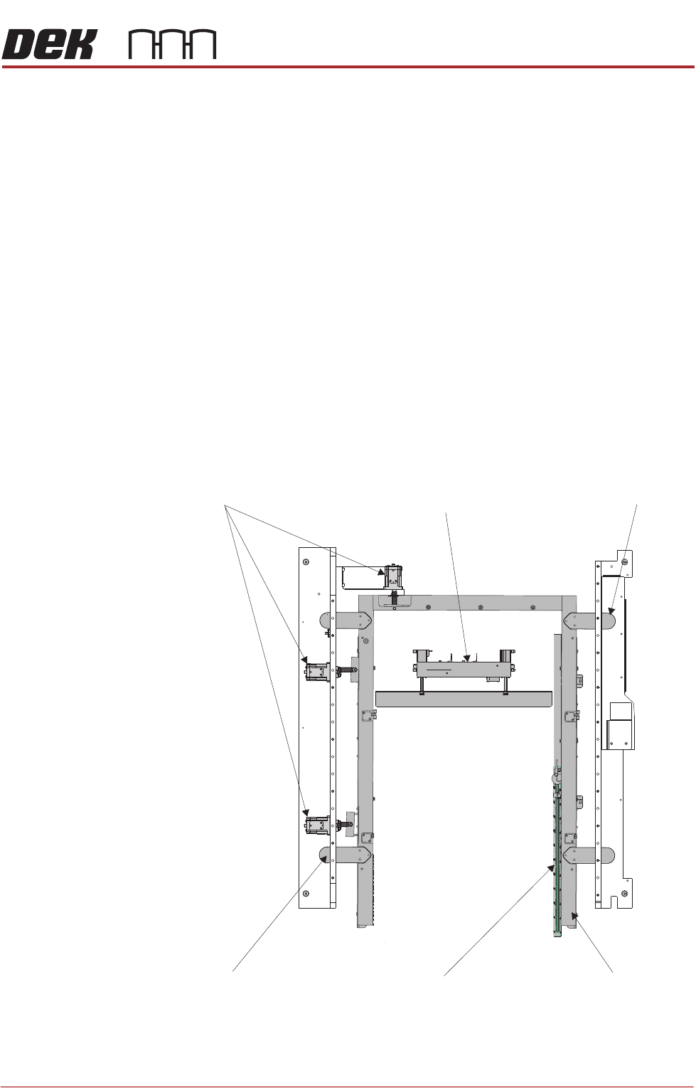
Machined C Chase The machined C chase is the receptacle for the stencil during printing opera-
tions. The machined C chase accommodates the standard 29” by 29” stencil
size. The print stencil is clamped into place by the machined C chase during the
print cycle.
There are two methods used for achieving correct position of the stencil within
the chase assembly:
• Screen Depth Adjuster
• Screen Change Mechanism
There are two image scales on the screen depth adjuster:
• Centre Justified Image Scale
• Front Justified Image Scale
Screen Alignment
Module
The screen alignment module enables adjustment of the machined chase to
achieve optimum stencil to board alignment prior to the print stroke. Actuators
move the print stencil in the X, Y and theta planes to nullify the misalignment
error signal from the vision system.
Figure 4-14 Machined C Chase - Screen Alignment
Screen Depth Adjuster
Screen Change Mechanism
Screen Alignment
(chase clamp)
Screen Alignment
(chase clamp)
Screen Alignment
(actuators)
Machined C Chase