Micron Technical Reference V9 Volume 1.pdf - 第58页
COVERS PRINTER COVERS 3.16 Technical Reference Manual Chapter Issue 11, Jan 17 7. Release the front and rear quarter-turn ring latch es located above the front and rear corner panels respectively . 8. Pull the top edge o…
COVERS
PRINTER COVERS
Chapter Issue 11, Jan 17 Technical Reference Manual 3.15
Upper Side Panels To remove an upper side panel, carry out the following:
1. Lift the sliding cover.
2. Lift the rear printhead cover.
3. Remove the safety cover.
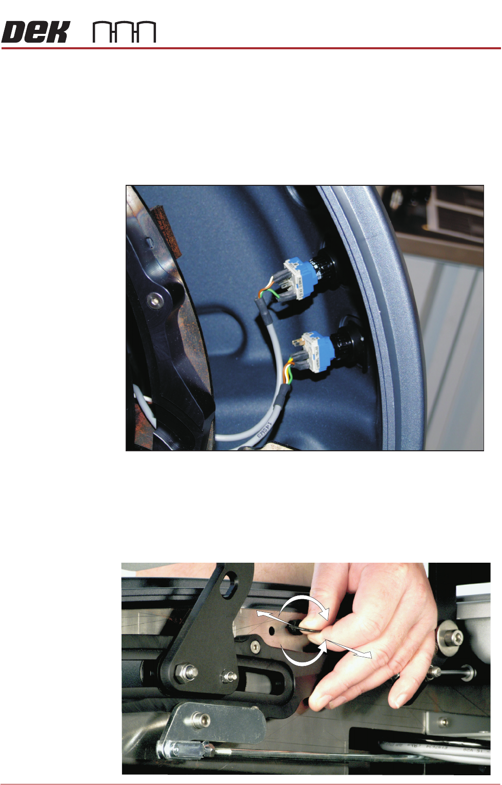
4. At the front of the upper side panel, remove the appropriate upper panel
switch contact blocks (System, Jog or Internal light.) The blocks are located
at the rear of the switch bezel.
5. The contact block can be separated from the bezel, (hold the body part to
remove the contact blocks, not the switch wires) by pulling it out of the bezel.
When refitting, the contact body is aligned with the bezel.
6. Release the quarter-turn ring latch fastener, located internally at the top front
of the cover.
Switches (System, Jog)
+
-
COVERS
PRINTER COVERS
3.16 Technical Reference Manual Chapter Issue 11, Jan 17
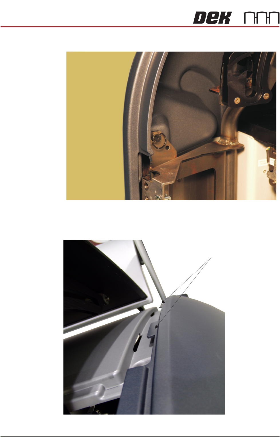
7. Release the front and rear quarter-turn ring latches located above the front
and rear corner panels respectively.
8. Pull the top edge of the cover out to release the locating tabs from the top
edge.
Quarter-Turn Ring Fastener
Panel Locating Tabs
COVERS
PRINTER COVERS
Chapter Issue 11, Jan 17 Technical Reference Manual 3.17
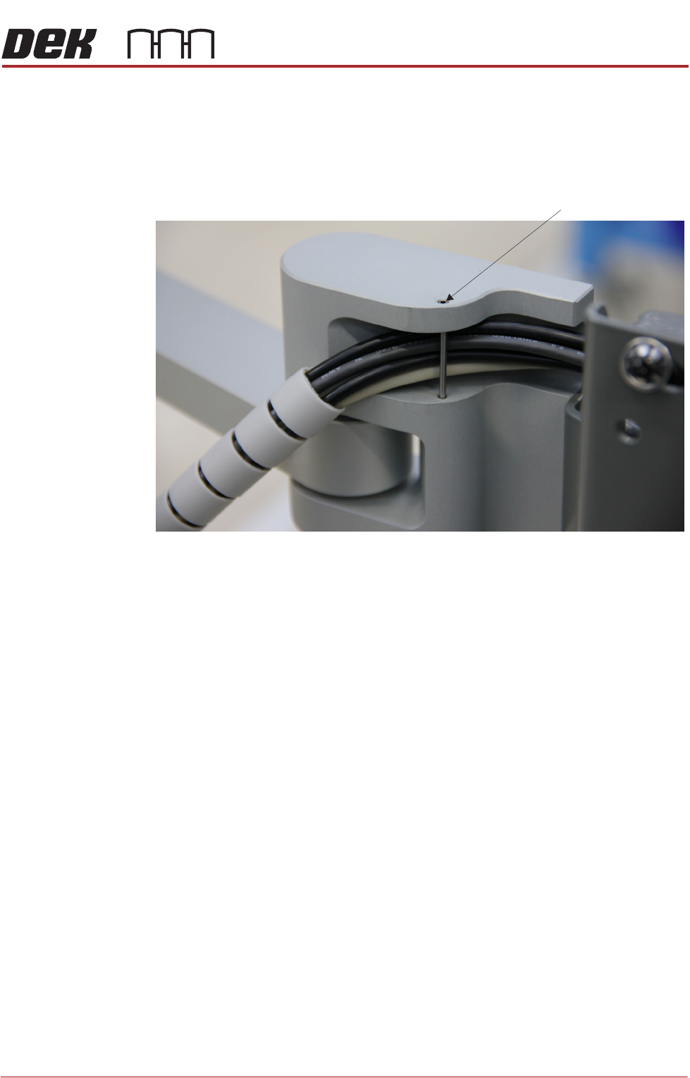
The panel can be ‘hinged’ away to release the bottom tabs from the support
rail. Lift the panel out of position.
NOTE
When refitting the right hand panel, ensure that the cables from the MMI are
routed in the support arm groove.
Dowel Pin