Micron Technical Reference V9 Volume 1.pdf - 第37页
SAFETY FEATURES GENERAL Chapter Issue 14, Feb 18 Technical Reference Manual 2.13 E Stop Module Shut Down If the E Stop loop is opened by pressing the E Stop or opening the printhead cover , an emergency stop is initia te…
SAFETY FEATURES
GENERAL
2.12 Technical Reference Manual Chapter Issue 14, Feb 18
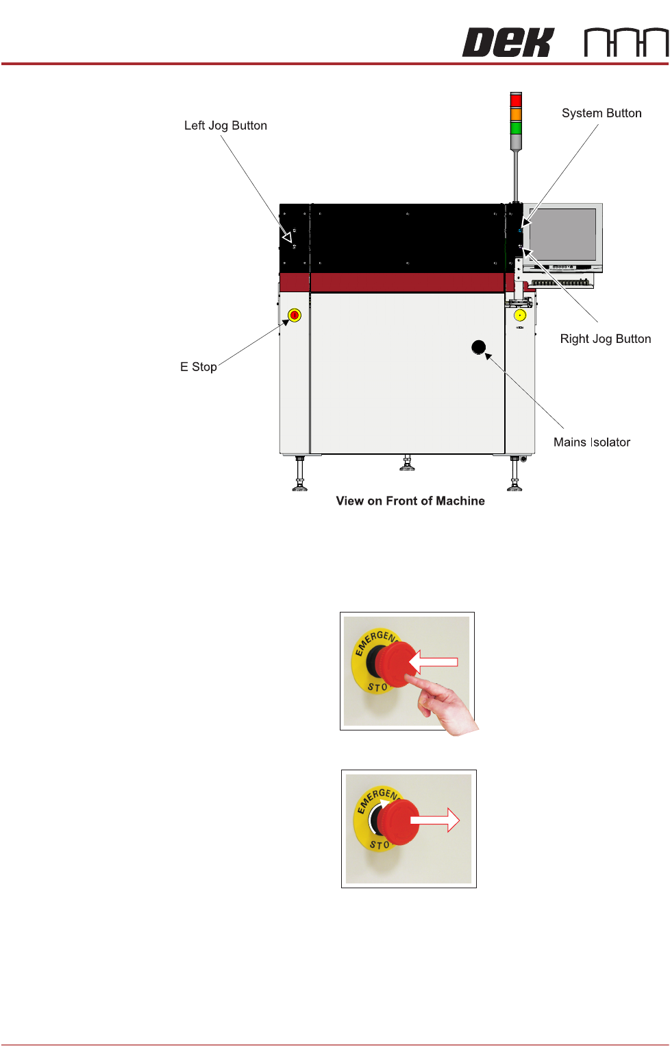
Figure 2-5 Type 5
Emergency Stop (E
Stop)
The machine is fitted with an E Stop which suspends all machine operations.
The switch is within easy reach of the operator and once pressed, the latching
switch requires resetting.
To reset the E Stop, turn the button clockwise until it unlatches.
Pressing the E Stop or opening the printhead cover cuts the servo axes power
supply. A warning of this condition is reported on the machine monitor.

SAFETY FEATURES
GENERAL
Chapter Issue 14, Feb 18 Technical Reference Manual 2.13
E Stop Module Shut
Down
If the E Stop loop is opened by pressing the E Stop or opening the printhead
cover, an emergency stop is initiated via the E Stop module. When actuated the
following areas of the machine are rendered inactive:
•Lid Bolt
• Moving Rail Stepper
• Print Carriage Servo (axis stopped before power is removed)
• Paste Cartridge Tilt Up/Tilt Down Pneumatic Actuator
• Paste Dispense Solenoid and Stepper Motor
• Rail System Front and Rear Belt Motor Drives
• Rising Table Brake (brake engages when power is cut)
• Rising Table Servo
• Squeegee/ProFlow Stepper Motor(s)
• System Lamp
• Underscreen Cleaner Paper Feed Motor
• Underscreen Cleaner Solvent Pump
• Underscreen Cleaner Squeegee Solenoid
• Vacuum Tooling Solenoid
• X Camera Motor (axis stopped before power is removed)
• X Forward, X Rear and Y Chase Alignment Stepper Motors
• Y Camera Motor (axis stopped before power is removed)
NOTE
The pass through lane belt motors on the Dual Lane machine continue running
when the printhead cover is open but stop when the E Stop is pressed.
Recovery When normal working conditions are restored, release the E Stop switch and,
when prompted by a screen message, press the System button.
Opening Covers Opening printhead covers are fitted with a cam interlock switch to protect
personnel from internal moving parts.
Lid Bolt Lid bolts are fitted to all opening printhead covers to prevent them from being
raised during the print cycle.
The lid bolts are withdrawn and the printhead cover may be raised when:
• Open Cover is requested by software
• Pause or stop is selected during a print cycle
• The E Stop is pressed

SAFETY FEATURES
GENERAL
2.14 Technical Reference Manual Chapter Issue 14, Feb 18
Jog Buttons The two button control switches or jog buttons are positioned such as to
maintain maximum safety for the operator whilst solvent priming or paper
feeding with the printhead cover open. This requires both buttons to be
depressed simultaneously for the function to become active. The use of these
buttons is dependent on the function selected on the machine monitor. During
normal operation these buttons control paper feed and solvent prime opera-
tions. When in maintenance mode, the two button control switches control the
movement of the following diagnostics:
• Print Carriage
• Squeegee Assembly
• Camera Axes
• Rail System
• Screen Alignment
• Rising Table
• ProFlow
Only one button is required to drive the selected mechanism, the two buttons
are used to drive the mechanism in opposite directions, ie jog forward or jog
back.