Micron Technical Reference V9 Volume 1.pdf - 第262页
PROACTIV ADJUSTMENTS AND SETTINGS 10.12 Technical Reference Manual Chapter Issue 5, Jan 15 NOTE Ensure that the rising table print reference height is set correctly before com- mencing, (the calibration re lies upon accu…
PROACTIV
ADJUSTMENTS AND SETTINGS
Chapter Issue 5, Jan 15 Technical Reference Manual 10.11
Squeegee
Pressure
Calibration
A force meter calibration jig and a squeegee pressure plate are required to
perform the squeegee pressure calibration.
NOTE
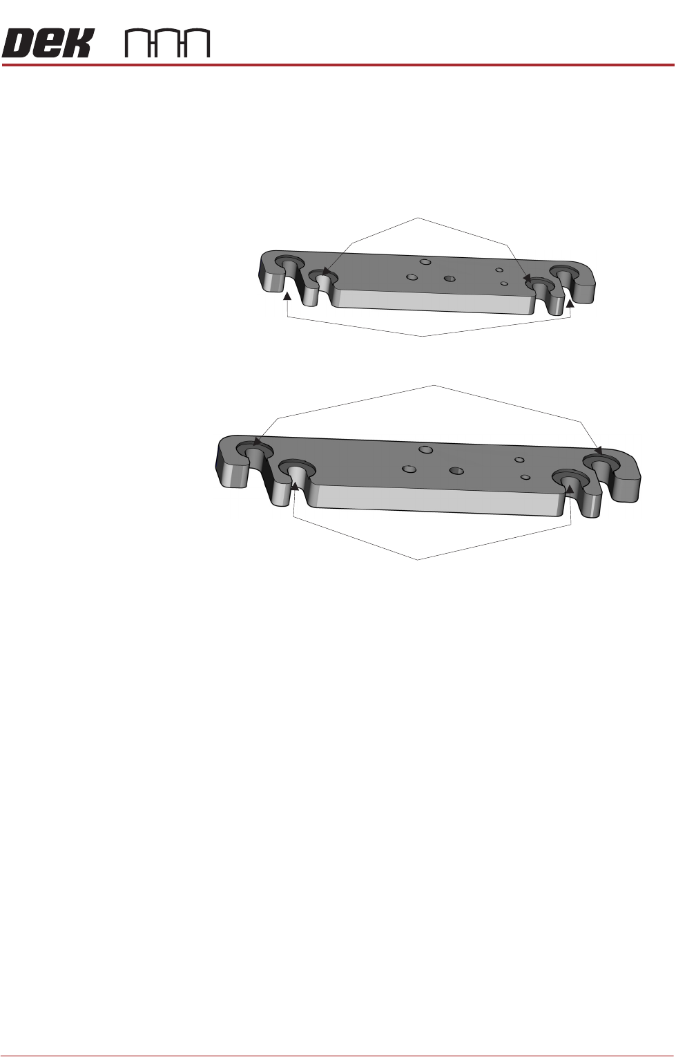
The front squeegee mount (foot) has two mounting locations, the inner locations
are for ProActiv, and the outer locations are for mounting the squeegee test jig.
Foot Assemblies
(showing the two squeegee mount locations)
Mount Locations for Pressure Test Jig or Standard Squeegee
Mount Locations for Standard Squeegee
Mount Locations for the Front ProActiv Squeegee Assembly
Mount Locations for the Rear ProActiv Squeegee Assembly

PROACTIV
ADJUSTMENTS AND SETTINGS
10.12 Technical Reference Manual Chapter Issue 5, Jan 15
NOTE
Ensure that the rising table print reference height is set correctly before com-
mencing, (the calibration relies upon accurate positioning of the table to make
a reference).
WARNING
BOARD CLAMPS. EXTREME CARE MUST BE EXERCISED WHEN WORKING IN
THE TOOLING AREA OF THE MACHINE TO AVOID INJURY. THE FOILS ON THE
FRONT AND REAR BOARD CLAMPS ARE VERY SHARP.
1. Select Open Cover Commands.
2. Select Carriage To Rear.
3. Select Unload Screen.
4. Open the front printhead cover.
5. Remove the screen from the machine.
6. Remove the tooling from the tooling plate.
7. Close the front printhead cover.
8. Press the System button.
9. Select Back.
10. Select Maintenance.
11. Select Calibrations.
12. Select Pressure.
13. Select Calibrat Readings. The rails are checked for the presence of a
board, the print carriage moves to the calibration position, the rear rail
moves to home position, the table homes and the board clamps are closed.
14. The machine cover is unlocked and the message ‘Fit the pressure calibra-
tion rig.’ is displayed with the following window:
15. Open the front printhead cover.
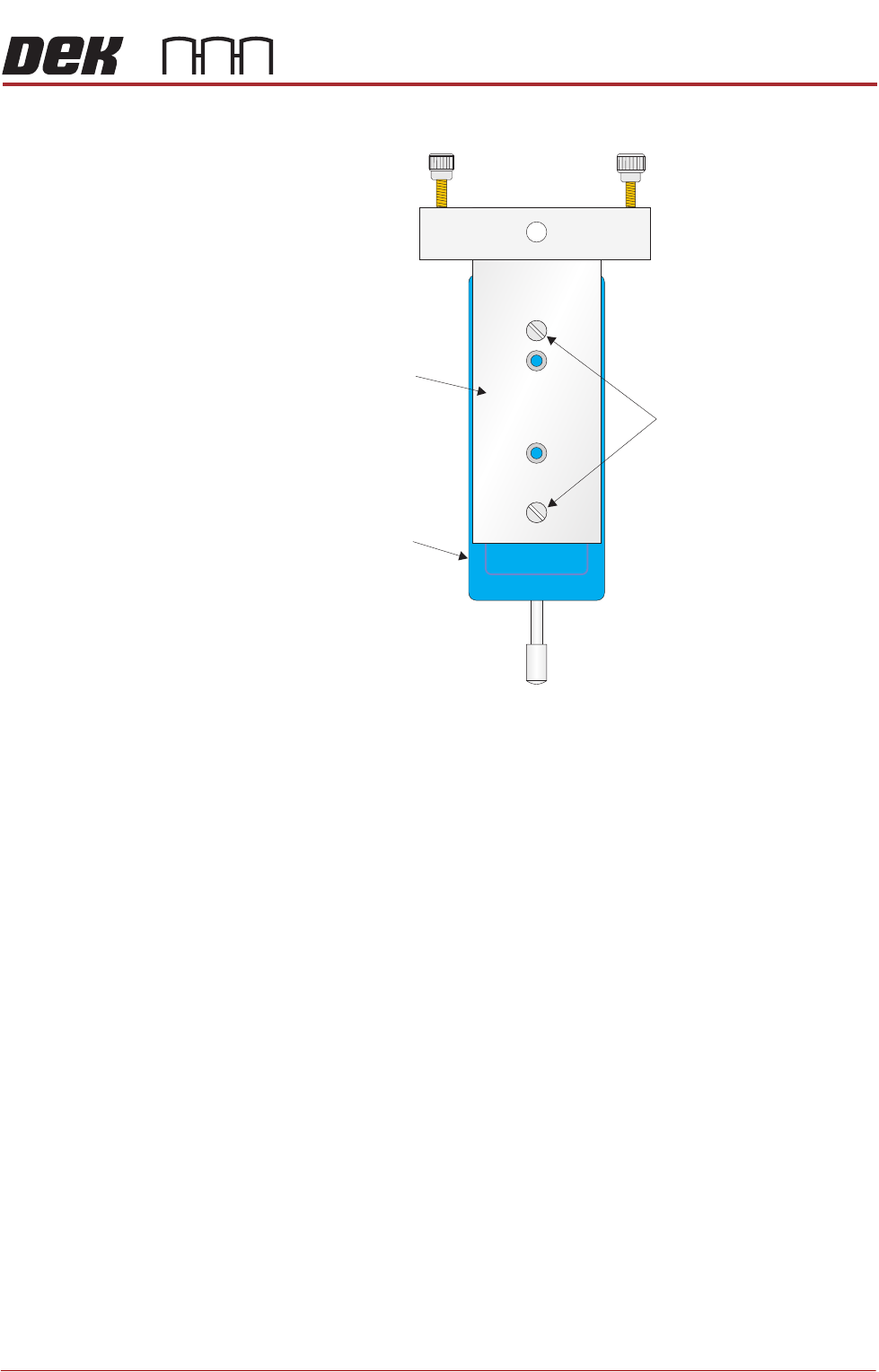
16. Ensure that the calibration jig is secured to the mounting plate as shown in
CALIBRATION DATA
Gain Factor
1.02
PROACTIV
ADJUSTMENTS AND SETTINGS
Chapter Issue 5, Jan 15 Technical Reference Manual 10.13
the following graphic:
17. Fit the calibration jig to the front squeegee position using the outer mounting
Mounting Plate
Mounting Holes
Calibration Jig
A
A
S
S