Micron Technical Reference V9 Volume 1.pdf - 第54页
COVERS PRINTER COVERS 3.12 Technical Reference Manual Chapter Issue 11, Jan 17 4mm Hexagonal Head Quarter-T urn Fasteners T o prevent personnel from having dire ct access to areas of the printer where safety hazards exis…
COVERS
PRINTER COVERS
Chapter Issue 11, Jan 17 Technical Reference Manual 3.11
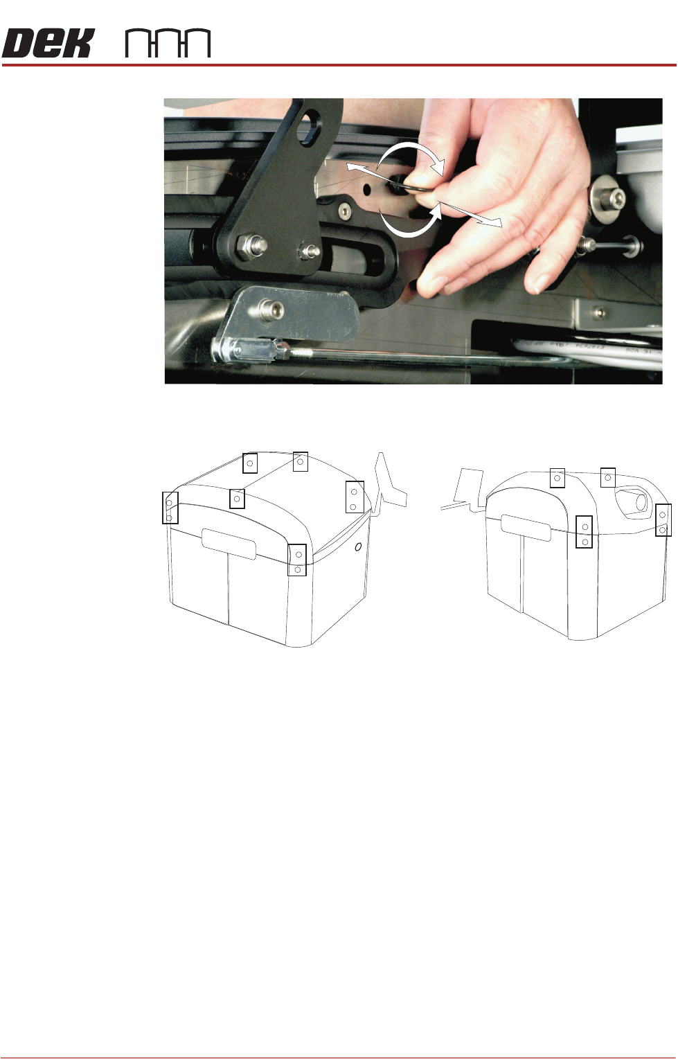
Figure 3-3 Quarter-Turn Ring Fastener
Figure 3-4 Fastener Locations
+
-
Locations (behind panels) of the Quarter Turn Ring Fasteners
Front Left Quarter
Rear Left Quarter
COVERS
PRINTER COVERS
3.12 Technical Reference Manual Chapter Issue 11, Jan 17
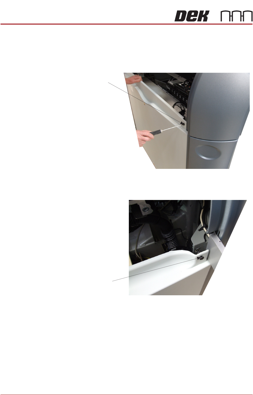
4mm Hexagonal
Head Quarter-Turn
Fasteners
To prevent personnel from having direct access to areas of the printer where
safety hazards exist, the front and rear panels each have two hexagonal head
fasteners. These fasteners are covered by the sliding cover, in the front of the
printer, and the rear printhead cover, at the back. Once access is gained, a
4mm Allen Key is used to release the fasteners on the top of the panel.
Figure 3-5 Front Safety Fasteners
Figure 3-6 Rear Safety Fasteners
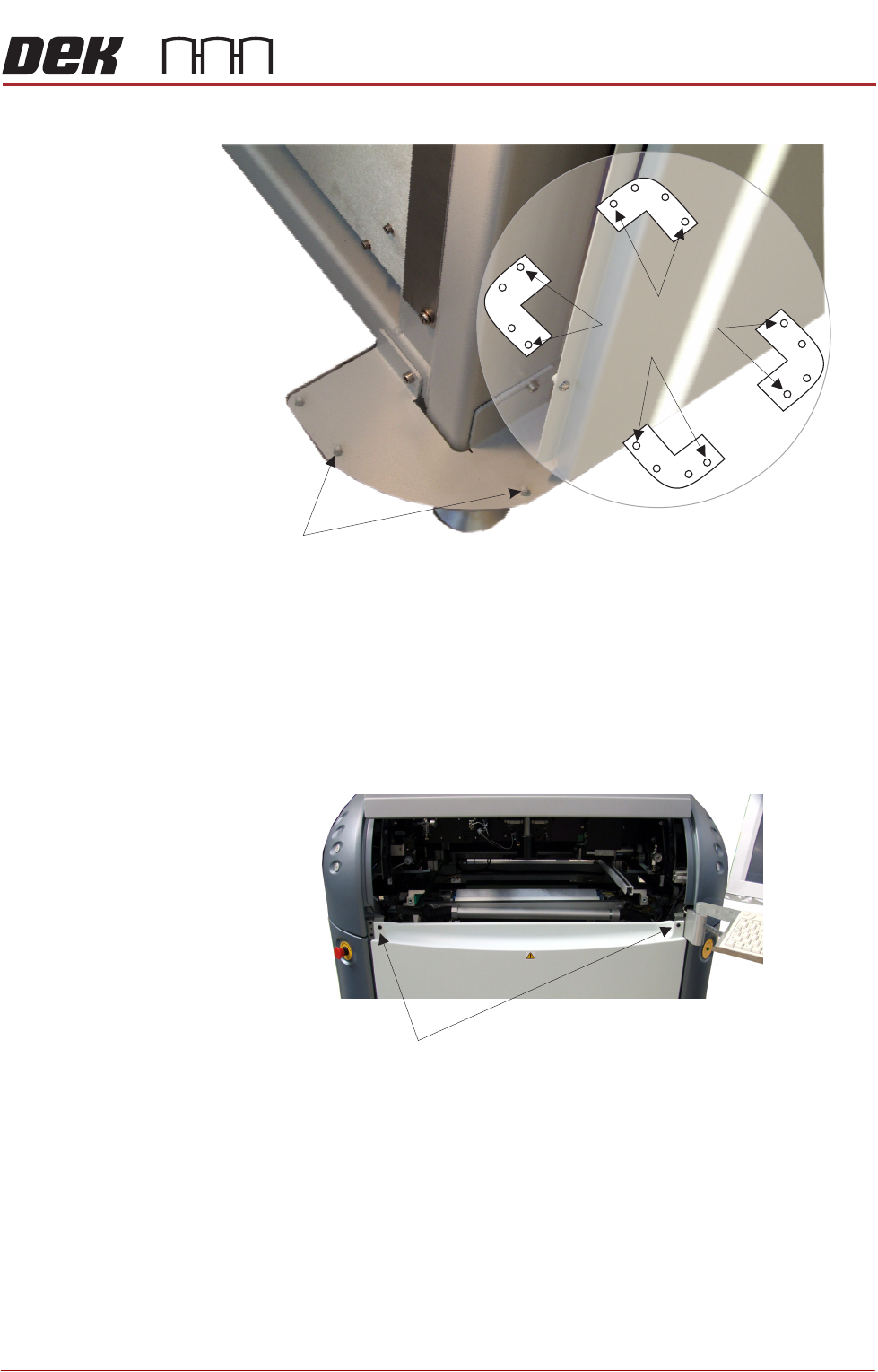
Locating Pins Side, corner, front and rear panels are secured on location pins at the base of
the printer. Plates mounted on each corner of the printer (see vignette below)
house the four pins; the two centre pins are for the corner panels and two outer
pins are for the side, front and rear panels.
4mm Hexagonal Head
Quarter-Turn Fastener
View on Printer Rear Right Corner
4mm Hexagonal Head
Quarter-Turn Fastener
View on Printer Front Right Corner
COVERS
PRINTER COVERS
Chapter Issue 11, Jan 17 Technical Reference Manual 3.13
Figure 3-7 Mounting Plates
Front Panel To remove the front panel, carry out the following:
1. Open the sliding cover.
2. Release the two quarter-turn ring fasteners located externally at the top
corners of the panel.
3. Tilt the top of the panel away from the printer and lift the panel clear of the
location pins at the bottom.
Rear Panel To remove the rear panel, carry out the following:
1. Lift the rear printhead cover.
2. Release the two quarter-turn ring fasteners located externally at the top
corners of the panel.
3. Tilt the top of the panel away from the printer and lift the panel clear of the
location pins at the bottom.
Corner Panel
Location Pins
View on Base of Printer
Location Pins
Side, Front &
Rear Panels
Quarter-turn fasteners