Micron Technical Reference V9 Volume 1.pdf - 第272页
PROACTIV REPLACEMENT PROCEDURES 10.22 Technical Reference Manual Chapter Issue 5, Jan 15 Removal This proced ure details the removal of the ProActiv unit from the prin ter . With the unit removed, the user can fit other …
PROACTIV
REPLACEMENT PROCEDURES
Chapter Issue 5, Jan 15 Technical Reference Manual 10.21
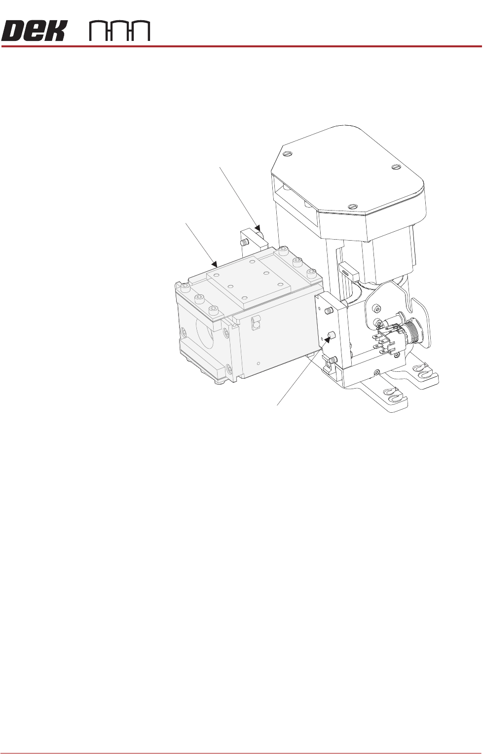
13. Carefully position the rear of the ProActiv squeegee mechanism (spring
beam assembly) into the print carriage so that both printhead mechanism
dowels locate into the print carriage locating holes. Secure the unit to the
print carriage by means of the four captive screws, using a 4mm Allen key.
14. Connect the following connectors to the print carriage, left-hand-side:
• Rear squeegee motor at 9SK17
• Front squeegee motor at 9SK16
• Home sensors at 9SK08
• Squeegee pressure amplifier at N3SK16
15. Connect the proximity switch sensor connector 9PL68 to 9SK68.
16. Fit the active squeegees to the squeegee mechanism.
17. Connect the active front squeegee drive 9PL74 to 9SK74.
18. Connect the active rear squeegee drive 9PL75 to 9SK75.
19. Remove the board from the tooling area.
Location Dowel
(2 positions)
Spring Beam
4mm Captive Screws
(4 positions)

PROACTIV
REPLACEMENT PROCEDURES
10.22 Technical Reference Manual Chapter Issue 5, Jan 15
Removal This procedure details the removal of the ProActiv unit from the printer. With the
unit removed, the user can fit other compatible applicator modules to the
printhead.
1. From the Ready page select Open Cover Commands.
2. Select Carriage to Front.
3. Select Back.
4. Select Shut Down.
5. Select Confirm.
6. Turn the mains isolator to the OFF position.
7. Open the printer front cover.
8. Disconnect active front squeegee drive 9PL74 from 9SK74.
9. Disconnect active rear squeegee drive 9PL75 from 9SK75.
10. Detach both squeegees and stow away. Before stowage, clean the units
using the Cleaning Guidance procedure (next section).
11. Disconnect 9PL68 from 9SK68, and cable tie it away from the mount
assembly.
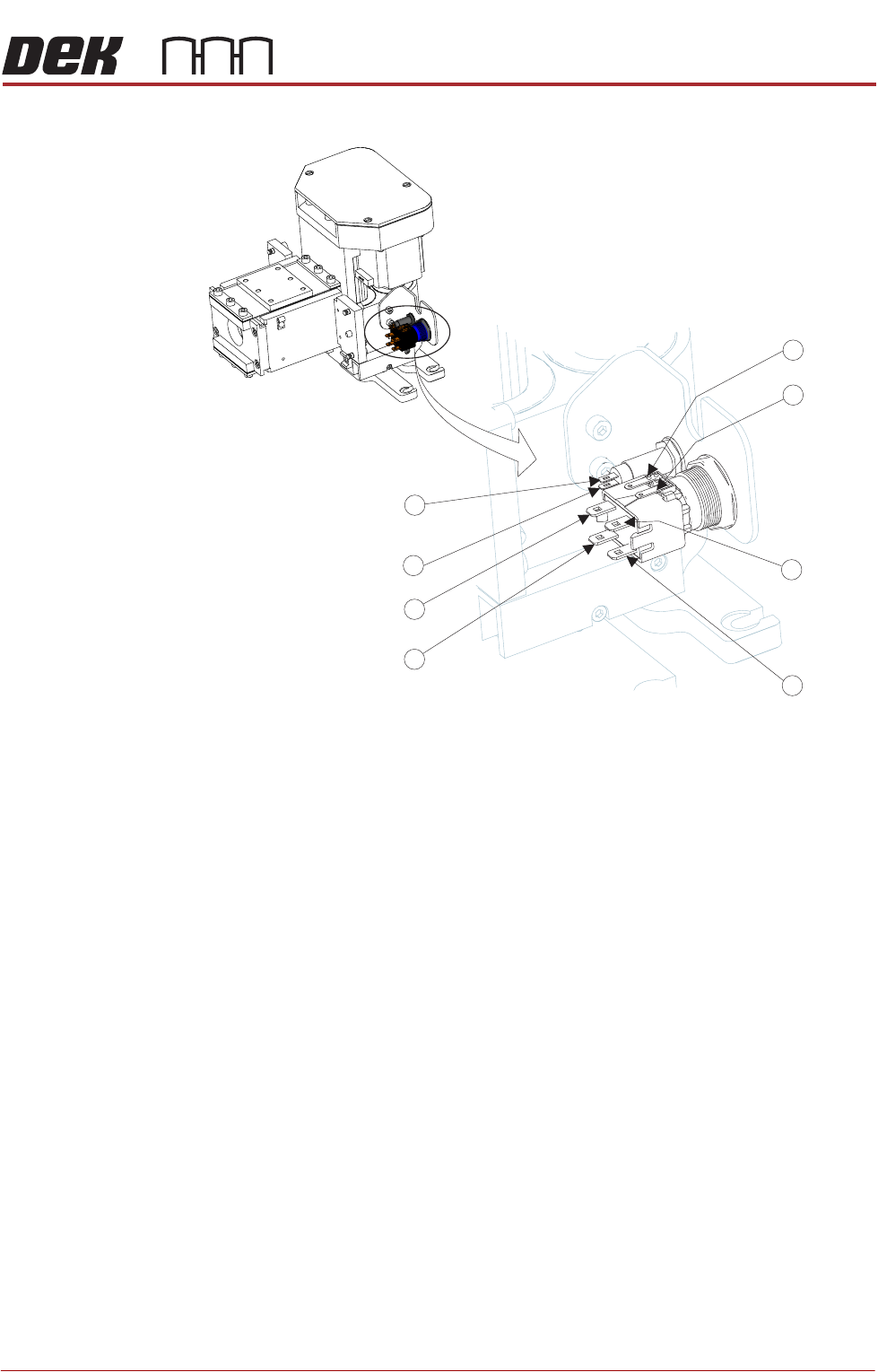
12. On the squeegee mechanism, disconnect the four spade connectors from
the enable switch/indicator, and the two spade connectors from the status
PROACTIV
REPLACEMENT PROCEDURES
Chapter Issue 5, Jan 15 Technical Reference Manual 10.23
indicator from N18PL08 (6) and N18PL05 (2) as follows:
Enable switch/indicator.
• Grey lead to Pin 1.
• Violet lead to Pin 2.
• No connection Pin 3.
• No connection Pin 4.
• Red lead to Pin 5 (marked +).
• Black lead to Pin 6 (marked -).
Status indicator.
• Brown lead to Pin 1 (Identified by the red dot on the indicator body.)
• White lead to Pin 2.
13. Cable tie the looms away from the mount assembly.
14. Disconnect the following connectors from the print carriage, left-hand-side:
• Rear squeegee motor at 9SK17
• Front squeegee motor at 9SK16
• Home sensors at 9SK08
• Squeegee pressure amplifier at N3SK16
15. Locate the four squeegee mount mounting screws; using a 4mm Allen key
undo the screws to release the squeegee mechanism and lift it free. Stow
5
6
3
2
1
4
2
1
Status
Status
Enable
Enable
Enable
Enable
Enable
Status
Enable
Status