Micron Technical Reference V9 Volume 1.pdf - 第219页
PRINT CARRIAGE MODULE OVERVIEW Chapter Issue 5, Aug 14 Technical Reference Manual 8.3 The print carriage enables the following modules to carry out their functions: • Printhead Assembly - to transverse across the stencil…
PRINT CARRIAGE MODULE
OVERVIEW
8.2 Technical Reference Manual Chapter Issue 5, Aug 14
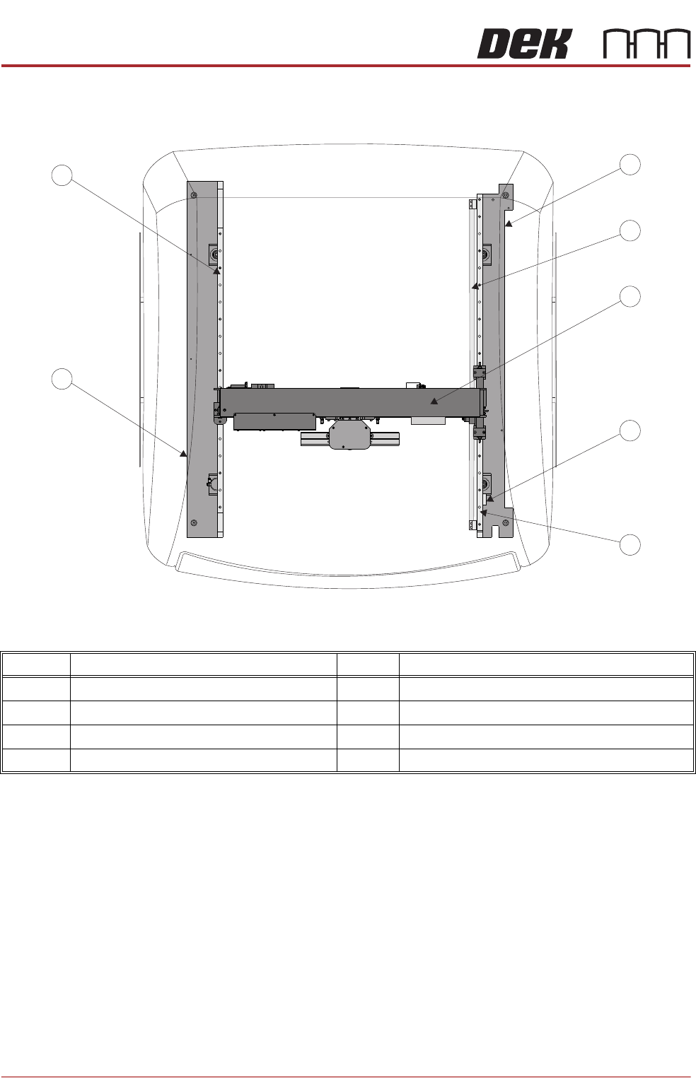
Item Description Item Description
1 Right Hand Printhead 5 Right Linear Guide Rail
2 Timing Belt 6 Left Hand Printhead
3 Print Carriage 7 Left Linear Guide Rail
4 Print Carriage Home Vane
Printhead Plan View
7
6
2
1
3
4
5

PRINT CARRIAGE MODULE
OVERVIEW
Chapter Issue 5, Aug 14 Technical Reference Manual 8.3
The print carriage enables the following modules to carry out their functions:
• Printhead Assembly - to transverse across the stencil in the Y direction
(print stroke - automatically set from the board width parameter)
• Paste Dispense Module - to supply paste at the required position of the
print stroke
• Screen Change Module - to perform a stencil load or stencil change
NOTE
Two types of the printhead assembly are available for fitment to the print
carriage:
a. Squeegee
b. ProFlow
Information on both types are detailed in the relevant module chapter of this
manual.
All positioning of the print carriage is referenced from the home position and
calculated in the machine software, taking into account:
• Board width
• Front and rear print limits
• Front rail justification
The print carriage only homes during initialisation, which can be from power-up
or exiting diagnostics.
I/O Node Board 3, located inside the print carriage extrusion, has an onboard
temperature and humidity sensor. For information on I/O Node Board 3 refer to
the Machine Control Chapter
For information on the print carriage solenoids refer to the Pneumatics Chapter
and the relevant module chapter.
PRINT CARRIAGE MODULE
ELECTRICAL SCHEMATIC
8.4 Technical Reference Manual Chapter Issue 5, Aug 14
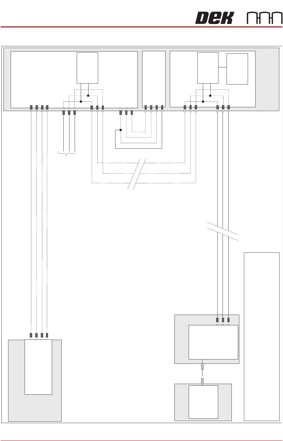
ELECTRICAL SCHEMATIC
N7SK2
24V US (Motor Logic)
M37 Power Supply Module
Print Carriage
Print Carriage Motor
Node 7
1
2
4
5
Servo DC Supply
0V Return
0V Return
1
2
3
4
Power Distribution
PCB
N7PL1
1
2
3
0V
Signal
24V
9SE03
0V
Signal
24V
(L)
Print Carriage
Home 9SE3
Fork Opto
M37PL17
N7PL4
7
2
3
CAN GND
CAN_L
CAN_H
CAN Out
N7SK3
7
2
3
CAN_L
CAN GND
I/O Node 3
N3SK3
2
3
7
CAN_H
CAN_L
CAN GND
CAN_H
PC
M36 Machine
Control Enclosure
USB
Motherboard
NextMove ES
(I/O Node 1)
1
2
4
CAN_H
CAN_L
CAN GND
M36PL35
N3SK2
2
3
7
CAN_H
CAN_L
CAN GND
CAN
Encoder/
Decoder
CAN
Encoder/
Decoder
Temperature
& Humidity
Sensor
NOTE
The breaks in the CAN Bus chain reflect that additional I/O N odes
may be fitted, refer to Machine C ontrol chapter for the com plete
CAN Bus chain. For print carriage solenoid schem at
ic see P neum at
ic
M odule chapter
.
CAN Bus