PatternPro Variable Pitch Guns.pdf - 第25页
21 24V Solenoid valve terminal block positions 21 P/N 1048257_03 2018 Nordson Corporation PatternPro Edition 02/18 2. Gently press against the edge of one of the terminal block retaining prongs to remove the terminal b…
20
P/N 1048257_03
2018 Nordson Corporation
PatternPro
Edition 02/18
Connect Triggering Device
Be sure to refer to the correct triggering device connection procedure for the
solenoid valve on your applicator.
For solenoids that do not have an M8 connection see the instruction below.
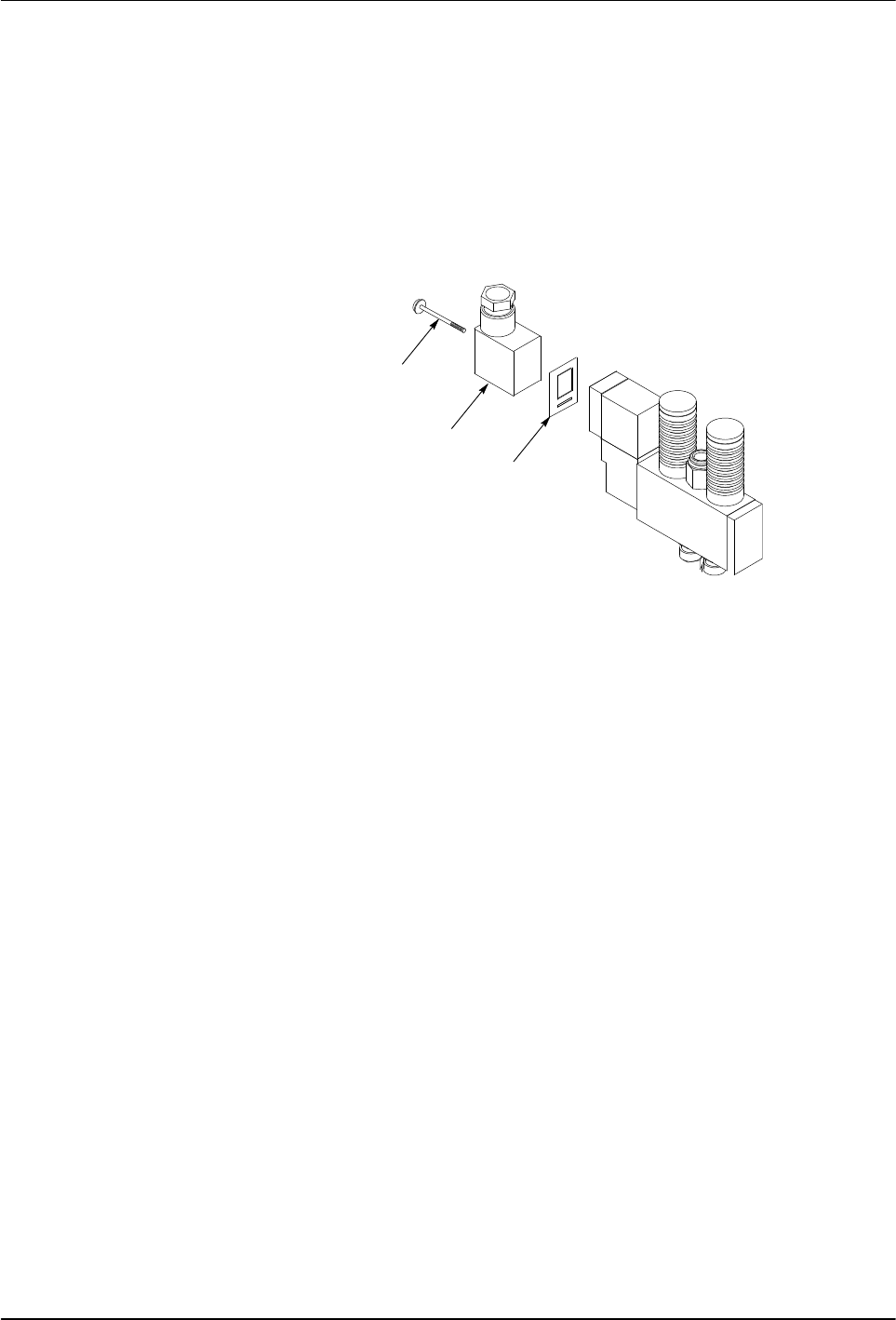
See Figure 5.
1. Remove the solenoid valve terminal block. Save the gasket that is
positioned between the terminal block and the valve.
4215012
1
2
3
Fig. 5 Removing the Solenoid Valve Terminal Block
1 Terminal block screw
2 Terminal block
3 Gasket
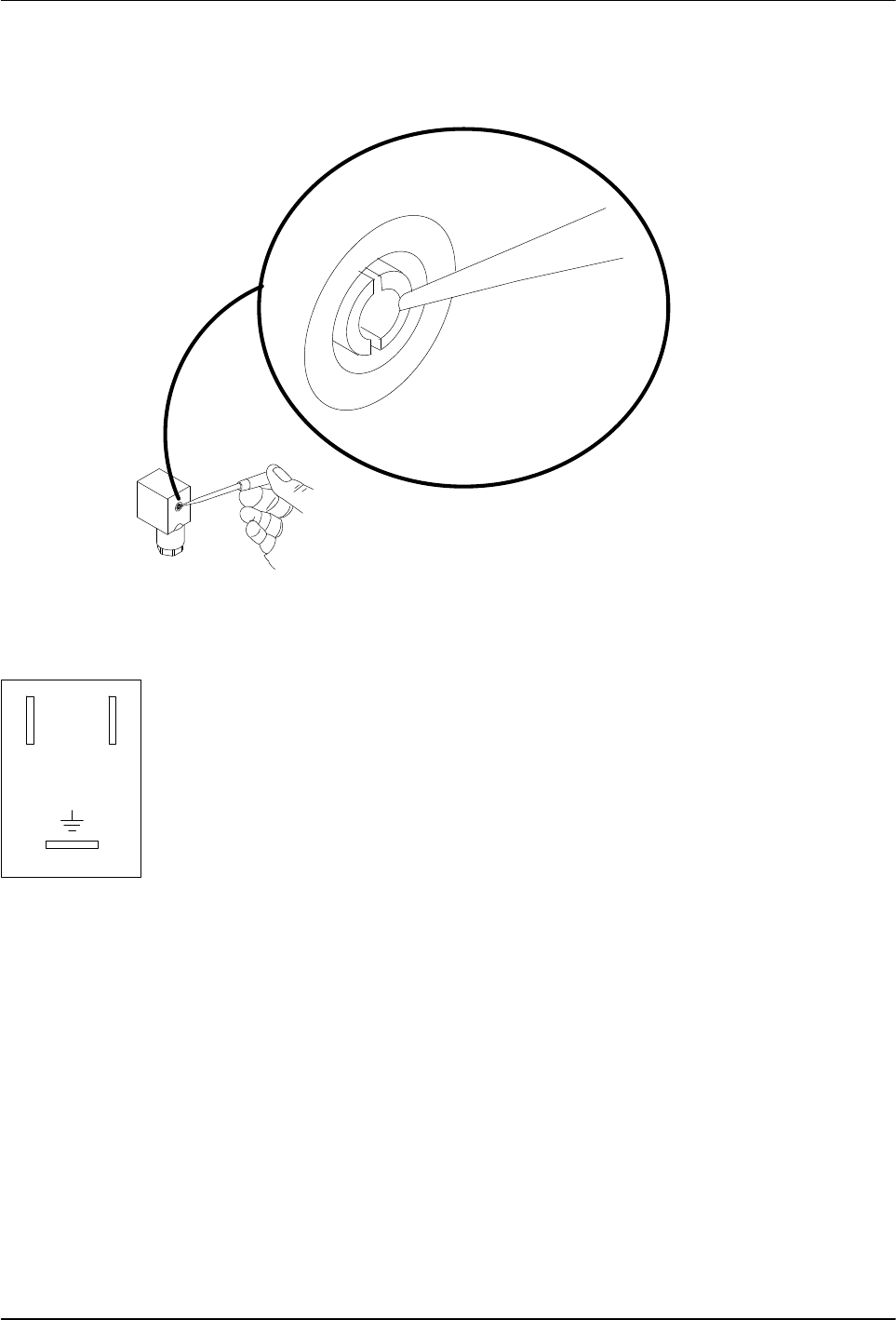
See Figure 6.
CAUTION: Do not attempt to pry the terminal block out of the housing. Doing
so can damage the electrical connection pins.
21
24V
Solenoid valve terminal
block positions
21
P/N 1048257_03
2018 Nordson Corporation
PatternPro
Edition 02/18
2. Gently press against the edge of one of the terminal block retaining
prongs to remove the terminal block from the housing.
4209007A
Fig. 6 Removing the Terminal Block from the Housing
NOTE: Solenoid valves must be rated for the output voltage of the triggering
device. Make sure the ratings match.
3. Thread a 0.75-0.34 mm
2
(18-22 AWG) three‐conductor cable through the
housing strain relief and then connect the positive and negative leads to
terminals 1 and 2 (polarity does not matter) and connect the ground wire
to the ground terminal. The terminal positions are marked on the bottom
of the terminal block.
4. Snap the terminal block back into its housing.
5. Align the gasket on the terminal block housing, plug the terminal block
into the solenoid valve, and secure it with the screw removed earlier.
6. Connect the three‐conductor cable to the triggering device. Refer to the
instructions that came with the triggering device.
7. Go to Connecting the Hose.
22
P/N 1048257_03
2018 Nordson Corporation
PatternPro
Edition 02/18
Connecting the Hose
Refer to the user's guide shipped with the hose for detailed hose installation
guidelines.
1. Do one of the following:
If an in‐line filter is to be used, remove the hose connector
preinstalled on the applicator and then install the in‐line filter. Refer to
the instruction sheet provided with the in‐line filter.
If no in‐line filter is used, check the tightness of the preinstalled hose
connector.
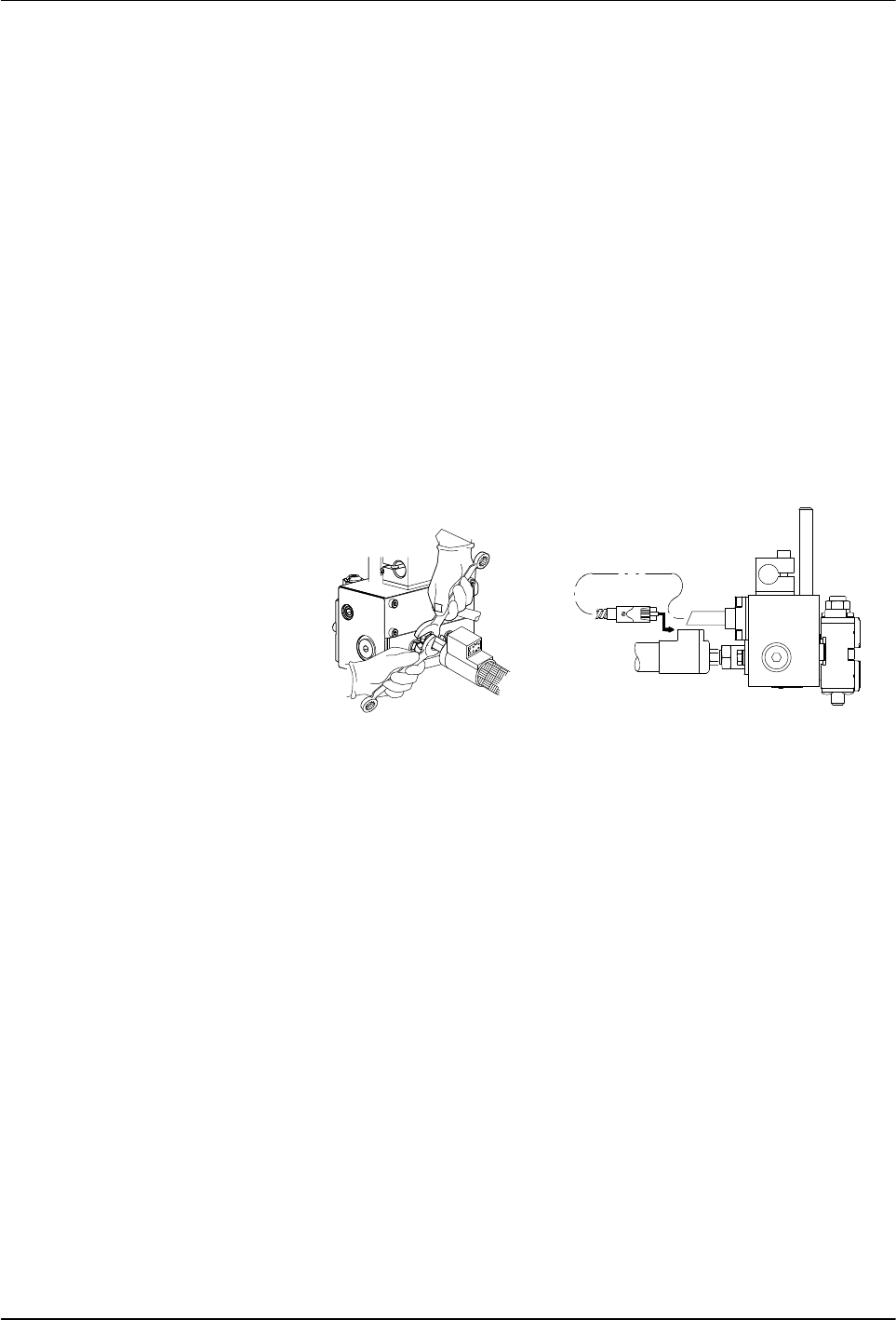
See Figure 7.
2. Connect the hose swivel fitting to the applicator hose connector. Use two
wrenches to tighten the hose fitting.
3. Connect the applicator cordset to the hose.
4. Connect the hose to the melter. Refer to the hose user's guide and/or the
melter product manual as needed.
5. Go to Flushing the applicator.
1
2
Fig. 7 Connecting the Hose to the applicator
1 Tightening the hose‐to‐applicator
fitting
2 Plugging in the cordset