PatternPro Variable Pitch Guns.pdf - 第26页
22 P/N 1048257_03 2018 Nordson Corporation PatternPro Edition 02/18 Connecting the Hose Refer to the user's guide shipped with the hose for detailed hose installation guidelines. 1. Do one of the following: If a…
21
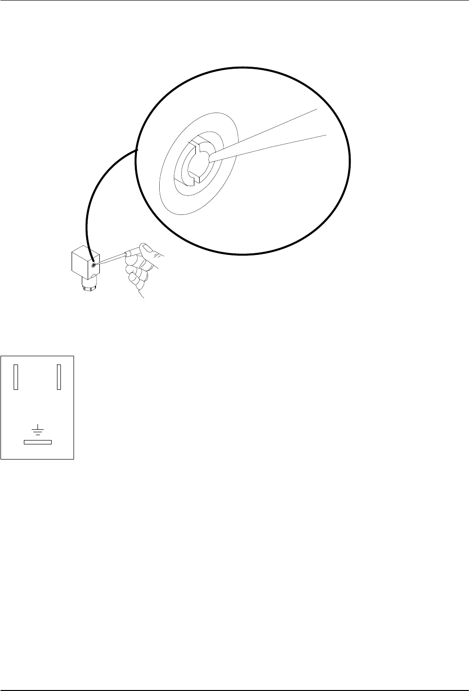
24V
Solenoid valve terminal
block positions
21
P/N 1048257_03
2018 Nordson Corporation
PatternPro
Edition 02/18
2. Gently press against the edge of one of the terminal block retaining
prongs to remove the terminal block from the housing.
4209007A
Fig. 6 Removing the Terminal Block from the Housing
NOTE: Solenoid valves must be rated for the output voltage of the triggering
device. Make sure the ratings match.
3. Thread a 0.75-0.34 mm
2
(18-22 AWG) three‐conductor cable through the
housing strain relief and then connect the positive and negative leads to
terminals 1 and 2 (polarity does not matter) and connect the ground wire
to the ground terminal. The terminal positions are marked on the bottom
of the terminal block.
4. Snap the terminal block back into its housing.
5. Align the gasket on the terminal block housing, plug the terminal block
into the solenoid valve, and secure it with the screw removed earlier.
6. Connect the three‐conductor cable to the triggering device. Refer to the
instructions that came with the triggering device.
7. Go to Connecting the Hose.
22
P/N 1048257_03
2018 Nordson Corporation
PatternPro
Edition 02/18
Connecting the Hose
Refer to the user's guide shipped with the hose for detailed hose installation
guidelines.
1. Do one of the following:
If an in‐line filter is to be used, remove the hose connector
preinstalled on the applicator and then install the in‐line filter. Refer to
the instruction sheet provided with the in‐line filter.
If no in‐line filter is used, check the tightness of the preinstalled hose
connector.
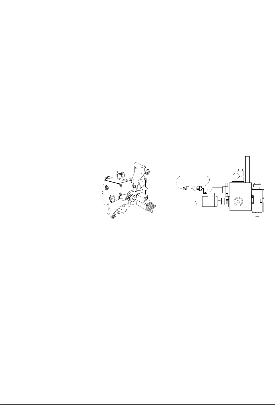
See Figure 7.
2. Connect the hose swivel fitting to the applicator hose connector. Use two
wrenches to tighten the hose fitting.
3. Connect the applicator cordset to the hose.
4. Connect the hose to the melter. Refer to the hose user's guide and/or the
melter product manual as needed.
5. Go to Flushing the applicator.
1
2
Fig. 7 Connecting the Hose to the applicator
1 Tightening the hose‐to‐applicator
fitting
2 Plugging in the cordset

23
P/N 1048257_03
2018 Nordson Corporation
PatternPro
Edition 02/18
Flushing the Applicator
Before operating the system, the applicator must be flushed to remove
residue left over from factory‐testing. Install the nozzles after this procedure.
For information on installing nozzles, refer to Maintenance.
NOTE: This equipment is factory tested with Nordson Type R fluid
containing polyester adipate plasticizer. Certain adhesives may react with the
Type R fluid residue to form a solid gum that can be difficult to remove.
Consult with the adhesive supplier to determine the compatibility of the
adhesive with Type R fluid.
1. Disconnect or turn off the solenoid valve triggering device.
2. Turn on the melter and allow it to reach operating temperature. Refer to
the melter manual for the startup procedure.
3. Place a drain pan under all applicators.
4. Flush according to the type of applicator module being used:
For standard Applicators
a. Dispense hot melt material from the applicator by manually triggering
the solenoid valve(s).
b. Stop dispensing when the flow of hot melt material is clear and free of
residue.