PatternPro Variable Pitch Guns.pdf - 第40页
36 P/N 1048257_03 2018 Nordson Corporation PatternPro Edition 02/18 DP4. Check an RTD 1. Disable the applicator. Refer to Safety . 2. Unplug the applicator cordset from the hose. 3. Allow the applicator to reach room t…
35
P/N 1048257_03
2018 Nordson Corporation
PatternPro
Edition 02/18
DP2. Check for a Clogged Nozzle or Module
1. Disable the applicator. Refer to Safety.
2. Remove the nozzle. Refer to Cleaning Nozzles in Maintenance for the
nozzle‐removal procedure.
3. Place the applicator back into operation.
4. Trigger the applicator:
Hot melt material flows—normal indication. Clean the nozzle. Refer to
Cleaning the Nozzles in Maintenance.
Hot melt material does not flow—the module is clogged. Replace the
module. Refer to Replacing the Rotating Disk and applicator Module
in Repair.
DP3. Check a Heater
1. Disable the applicator. Refer to Safety.
2. Unplug the applicator cordset from the hose.
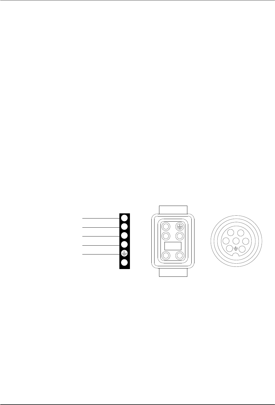
3. See Figure 10. Test for continuity across the heater circuit (pins 1 and2):
Continuity okay—normal indication. Return to the Troubleshooting
Table.
No continuity—the heater is defective. Replace the heater. Refer to
Replacing a RTD or Heater in Repair.
4209011A
1
2
3
4
5
6
1
2
3
5
HEATER
HEATER
RTD
RTD
GND
4
12
34
5
Fig. 10 Applicator Cordset Pins
36
P/N 1048257_03
2018 Nordson Corporation
PatternPro
Edition 02/18
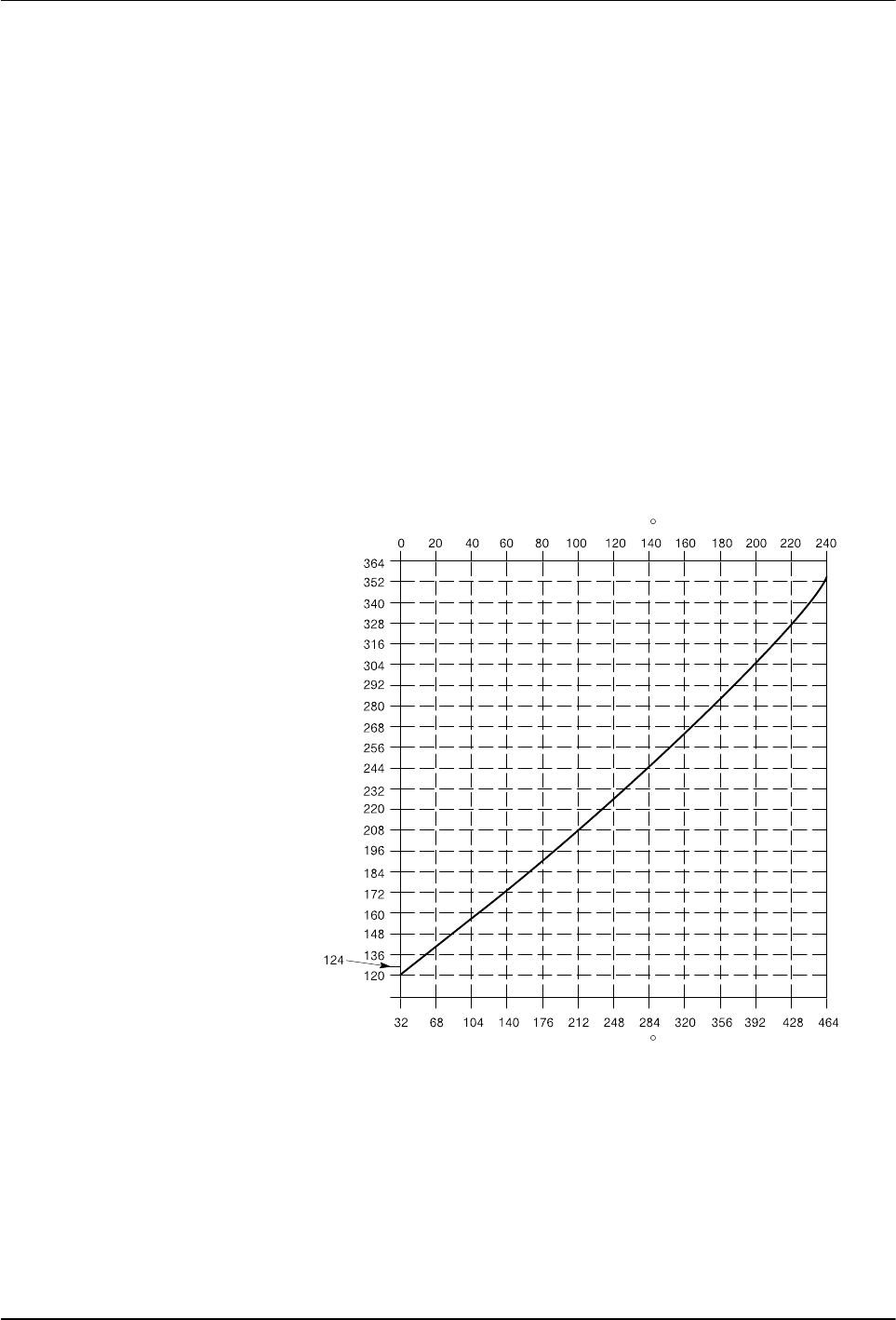
DP4. Check an RTD
1. Disable the applicator. Refer to Safety.
2. Unplug the applicator cordset from the hose.
3. Allow the applicator to reach room temperature or use a pyrometer to
determine the temperature of the applicator.
See Figure 10.
4. When the applicator temperature is known, measure the resistance
across the RTD circuit (pins 3 and 5).
5. See Figure 11 to determine the expected resistance of RTD at the known
temperature. Compare the expected and measured resistance values:
Measured resistance is within the expected range—normal
indication. Return to the Troubleshooting Table.
Measured resistance is not within the expected range—the RTD is
defective. Replace the RTD. Refer to Replacing a RTD or Heater in
Repair.
4209012A
Resistance
in Ohms
Temperature in F
Temperature in C
Nickel RTD
Fig. 11 RTD Resistance vs. Temperature

37
P/N 1048257_03
2018 Nordson Corporation
PatternPro
Edition 02/18
Repair
Refer to these repair procedures as needed. For repair procedures not
included in this section, refer to the instructions supplied with the
replacement part.
Replacing a RTD or Heater
Resistance temperature detectors (RTD) are hardwired through the
applicator cordset. If an RTD fails, the entire applicator cordset should be
replaced. Heaters are located inside the applicator body and can be replaced
individually without replacing the entire cordset.
The following procedure describes the replacement of an RTD and heater.
1. De‐energize the system and disable the applicator. Refer to Safety.
2. Unplug the applicator cordset from the hose.
3. (Optional) Relieve system hydraulic pressure. Refer to Safety.
4. (Optional) Using two wrenches, disconnect the hose from the applicator.
NOTE: Steps 3 and 4 are not necessary if the applicator is easily
accessible and can be serviced without the need to disconnect the hose.
See Figure 12.