PatternPro Variable Pitch Guns.pdf - 第43页
39 P/N 1048257_03 2018 Nordson Corporation PatternPro Edition 02/18 Replacing a RTD or Heater (contd) To replace the RTD a. Disconnect the ground lead from the applicator body and remove the cordset. b. Install a new c…
38
P/N 1048257_03
2018 Nordson Corporation
PatternPro
Edition 02/18
5. Remove the applicator body cover, by loosening and removing the Allen
head screws.
6
5
4
3
2
1
7
8
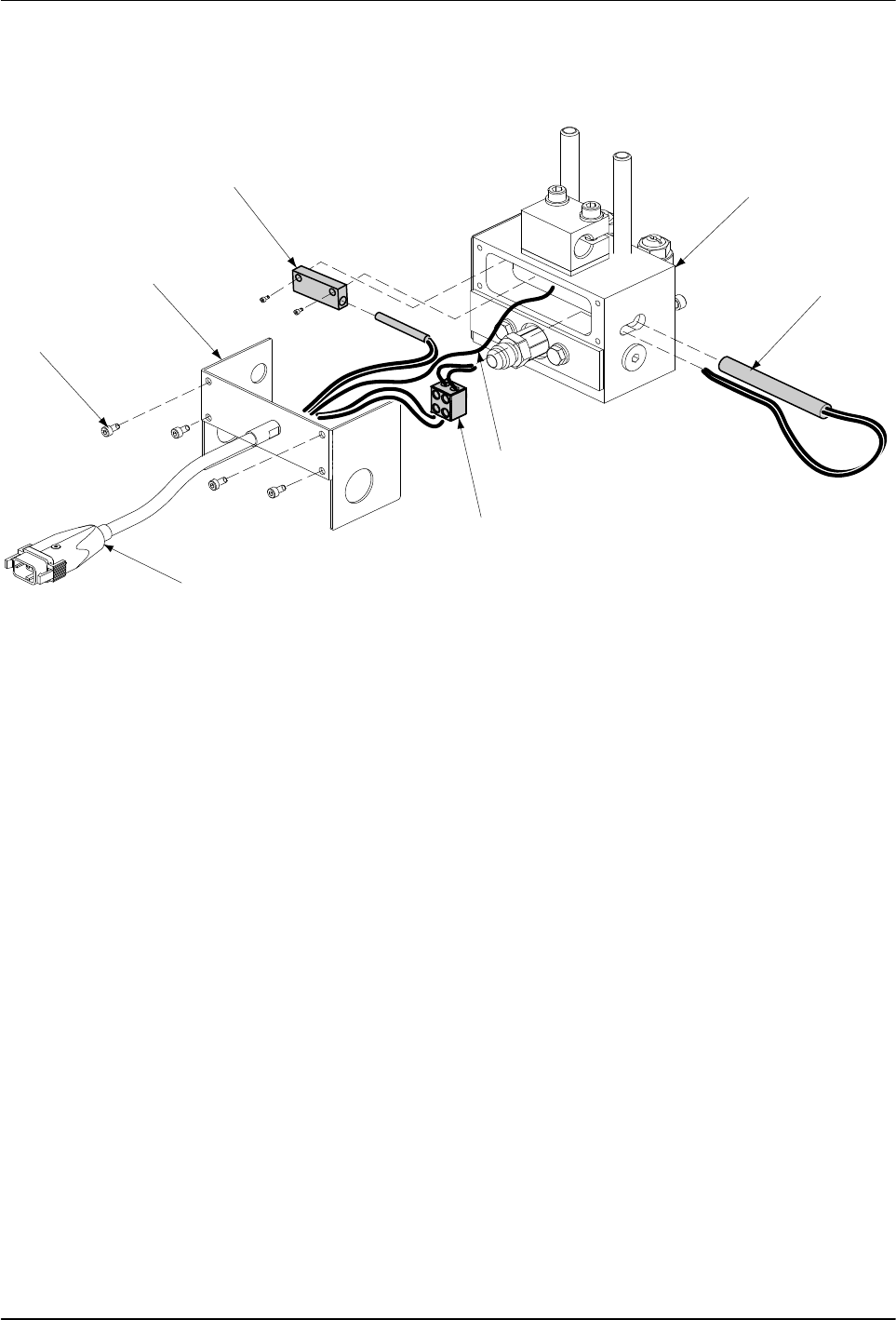
Fig. 12 Replacing the RTD or Heater
1 Applicator body
2 Heater
3 Ground lead
4 Terminal block
5 Cordset
6 Allen head screws
7 Applicator body cover
8 RTD block
6. Disconnect the cordset leads from the terminal block. If the heater is
being replaced, disconnect the heater leads from terminal block.
7. Remove the RTD and heater:

39
P/N 1048257_03
2018 Nordson Corporation
PatternPro
Edition 02/18
Replacing a RTD or Heater (contd)
To replace the RTD
a. Disconnect the ground lead from the applicator body and remove the
cordset.
b. Install a new cordset and insert the RTD in the applicator body by
tightening the screws.
c. Reconnect the ground lead to the applicator body.
To replace the heater
a. If necessary, trim the leads of the new heater to match the leads of
the old heater.
b. Insert the heater in the applicator body.
c. Insert each heater lead into the terminal block and tighten the terminal
block screws.
d. Insert the heater leads from the cordset into the terminal block and
tighten the terminal block screws.
8. Check the internal applicator wiring for signs of damage and the terminal
block connections for tightness.
9. Reinstall the applicator body cover, by reinstalling and tightening the four
Allen head screws.
10. If the hose was removed earlier, use two wrenches to connect the hose to
the applicator.
11. Plug the applicator cordset into the hose.
12. Restore the system to normal operation.
40
P/N 1048257_03
2018 Nordson Corporation
PatternPro
Edition 02/18
Replacing the Rotating Disk and Applicator Module
WARNING: System or material pressurized. Relieve pressure. Failure to
observe this warning may result in serious injury.
1. De‐energize the system and relieve system pressure. Refer to Safety.
2. Place a drain pan under the nozzles and trigger the applicator modules to
relieve any system pressure which may have accumulated.
3. If applicable, remove the nozzle from the applicator module.
See Figure 13.
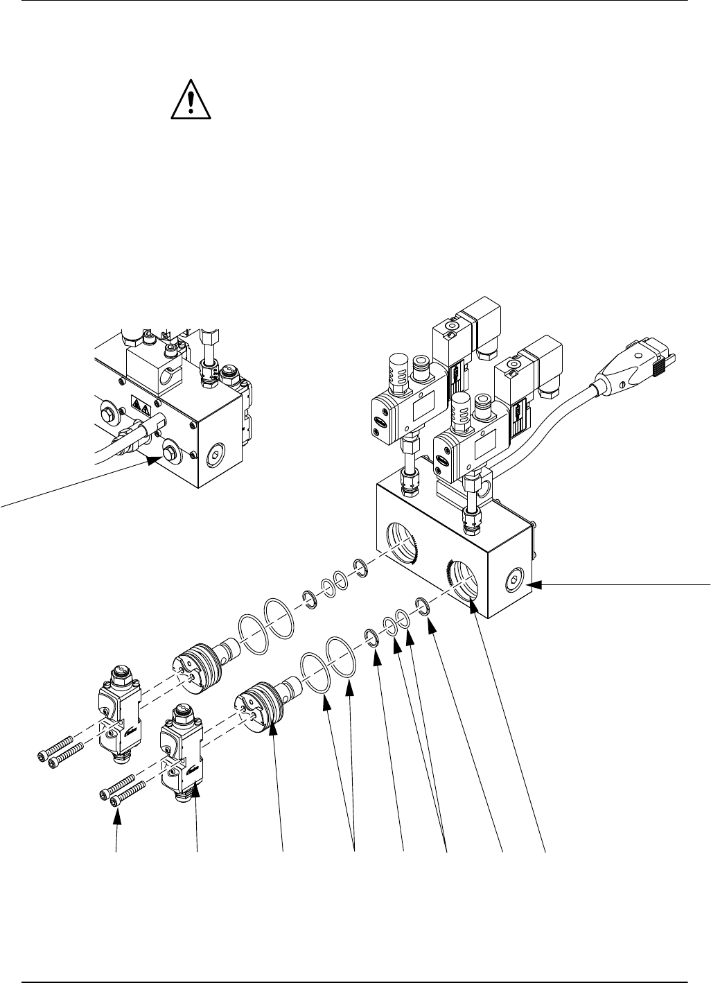
4. Loosen the two hexagon head screws located on the back of the
applicator body to remove rotating disk with O‐rings, and applicator
module
2
7
1
8659493
Fig. 13 Replacing the Rotating Disk and applicator Modules
1 Hexagon head screws
2 Applicator body
3 Disk cavity
4 O‐rings
5 O‐rings
6 Rotating disks
7 Mounting screws
8 Applicator modules
9 Back up rings