252301 Issue 2.0.pdf - 第46页
GEM Manual for DEK Printers Capabilities I ssue 2.0 June 9th, 2011 page 46 of 156 5.11 Limits Monitoring The DEK printer is ca pable of monitoring limits on selected status variables and discrete varia bles. These variab…
GEM Manual for DEK Printers Capabilities
Issue 2.0 June 9th, 2011 page 45 of 156
Comments Host Equipment Comments
<-- S6F11
Operator reads first message and presses Accept
button.
[IF] Acknowledge Terminal Message event
enabled [THEN] send event report.
Second message will be displayed.
[IF] text page contains more lines then page size
[THEN] Up/Down key will be available to scroll
through message.
Operator reads second message and presses
Accept button
[IF] Acknowledge Terminal Message event
enabled [THEN] send event report.
Host acknowledges event. S6F12 -->
5.9 Error Messages
This capability provides reporting of communications link errors to the host. All of the stream 9
messages as define in SEMI standard E5 are supported. The message structures are included in
section 4.9.
5.10 Clock
The DEK printer maintains an internal, host viewable, clock that is used for event report time
stamps. In order to differentiate between near simultaneous events, the clock has a precision of
0.01 seconds. It is not guaranteed to be accurate to the same level.
Note that the host must use the set time message S2F31 to synchronise the equipment. This
message contains the TIME variable defined in the machine variables, which has a precision of
1 second when the 12 byte format is used. When the 16 byte format is used it has a precision of
0.01 of a second. The format that is in use depends on the value of variable TimeFormat.
Scenarios:
Host requests that the equipment time is set:
Comments Host Equipment Comments
Set time TIME = Host time S2F31 -->
Adjust equipment to host time offset.
<-- S2F32 Acknowledge new time.
Host requests equipment current time:
Comments Host Equipment Comments
Time request S2F17 -->
<-- S2F18 Value TIME = host offset time sent.

GEM Manual for DEK Printers Capabilities
Issue 2.0 June 9th, 2011 page 46 of 156
5.11 Limits Monitoring
The DEK printer is capable of monitoring limits on selected status variables and discrete variables.
These variables are identified in section 5.5. The printer provides seven configurable limits that may be
applied to each variable. When one of these limits is crossed a collection event is generated. The event
can be used to alert the host that the variable has crossed a limit.
5.11.1 Definitions
Limit - Used in this section to represent the set of variable limit attributes that completely describe a
variable monitoring "barrier." The attributes include VID, Units, UPPERDB, LOWERDB,
LIMITMAX, and LIMITMIN. In some contexts it may be interpreted more narrowly as the
combination of UPPERDB and LOWERDB.
LIMITIDn - Refers to the identifier of a specific limit (as defined by UPPERDB and LOWERDB)
among the set of limits for a monitored equipment variable. LIMITIDs are consecutively numbered,
beginning at one through the number of limits possible (seven minimum).
Monitoring Zone - A subset of the possible range of values for a variable of interest to the host. A
single limit divides the range into two zones. Multiple limits may be combined to divide the range even
further.
Zone Transition - The movement of a variable value from one monitoring zone to another. This
transition is a collection event and has a corresponding CEID.
Deadband - An overlap of two zones implemented to prevent constant zone transitions by a variable
sitting on or near a limit (i.e. "chattering").
UPPERDB - A variable limit attribute that defines the upper boundary of the deadband of a limit. The
value applies to a single limit (LIMITID) for a specified VID. Thus, UPPERDB and LOWERDB as a
pair define a limit.
LOWERDB - A variable limit attribute that defines the lower boundary of the deadband of a limit.
The value applies to a single limit (LIMITID) for a specified VID. Thus, UPPERDB and LOWERDB
as a pair define a limit.
UPPER ZONE - The range of values lying above a limit.
LOWER ZONE - The range of values lying below a limit.
LIMITMAX - The maximum value for any limits of a specific equipment variable. This value is set
by the equipment manufacturer and typically coincides with the maximum value allowed for the
monitored variable.
GEM Manual for DEK Printers Capabilities
Issue 2.0 June 9th, 2011 page 47 of 156
5.11.2 Monitoring Limit Characteristics
A limit is defined by a set of attributes that include the variable (VID) to which the limit corresponds,
the units of that variable, the maximum and minimum possible values of the limit (LIMITMAX and
LIMITMIN) and the specific borders of the limit (UPPERDB and LOWERDB).
There is a limitation to the values of UPPERDB and LOWERDB which may be stated as:
LIMITMAX>UPPERDB>LOWERDB>LIMITMIN
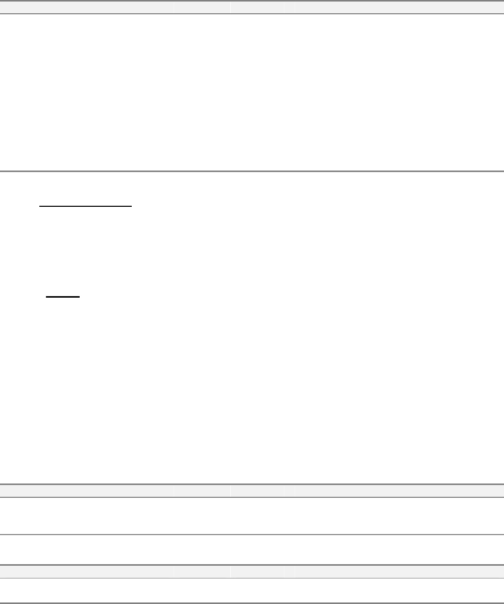
Example of how Limits can be applied to monitor a variable:
Limit 1
Limit 2
Limit 3
Limit 4
Limit 5
Limit 6
Limit 7
Nominal
Upper Spec. Limit
Lower Spec. Limit
Upper Control Limit
Lower Control Limit
Minimum Limit
Maximum Limit
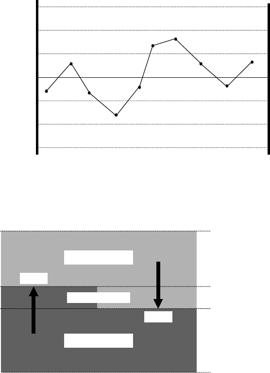
A limit divides the possible range of variable values into two parts, the upper zone and the lower zone.
At any time, the monitored variable is considered to be in one and only one of these zones. However,
as these two zones have an area of overlap. This is called the deadband.
UPPER ZONE
LOWER ZONE
DEAD BAND
Event
Event
LIMITMAX
LIMITMIN
UPPERDB
LOWERDB
The deadband is a key concept of limits monitoring, especially for floating point variables. Its purpose
is to prevent a phenomenon known as chattering (the repeated changing of zones due to small, rapid
fluctuations in variable value while near the zone boundary). In practice, the value of a variable must
reach the opposite boundary of the deadband before a zone transition can occur. Thus, if a variable's
value reaches the UPPERDB and moves into the upper zone, it will not return to the lower zone until it
falls back to the LOWERDB. The difference between UPPERDB and LOWERDB should always be
greater than the typical amplitude of those fluctuations, which are deemed insignificant. In some cases,
the width of the deadband may set to zero (UPPERDB = LOWERDB). At first glance, this would seem
to make indeterminate the current zone when an integer value sits on the limit. However, this is not the
case, when movement of the value is considered.