00192328-01.pdf - 第57页
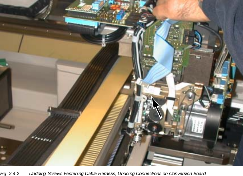
SIPLACE S-25 HM 2 Retrofitt. Instruct. RV6-DLM1 Head & Nozzle Chang. RV6 Standa rd (Optionen) 02/01 Issue 2.4 Sequence: Ins talling the Hardware 55 Å Und o the s crew fas tening the ca ble clam p that h olds the ca…
2 Retrofitt. Instruct. RV6-DLM1 Head & Nozzle Chang. RV6 Standard (Optionen) SIPLACE S-25 HM
2.4 Sequence: Installing the Hardware 02/01 Issue
54
'H,QVWDOOLQJ6HJPHQW5HYROYHU+HDG59'/0
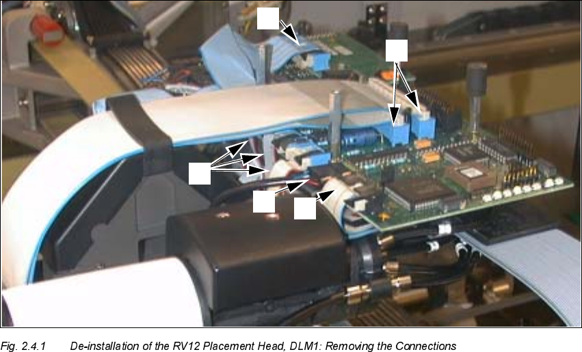
.H\
1. Ribbon cable "Vacuum board"
2. Round cable "Revolver head" (motor, tachometer)
3. 3 ribbon cables "Stepped motors/Photoelectric barrier"
4. 1 ribbon cable "Illumination PCB camera (illlumination board)
5. 2 ribbon cables, wide
Å Remove the 4 protective covers from the placement head: Unscrew the socket hex head cap
screws M3 and M2.5.
Å Undo the connectors of the front part of the placement head at the "Conversion board, small
axis" and on the illumination board (see: Fig. 2.4.1 -> 1 to 5).
2 Retrofitt. Instruct. RV6-DLM1 Head & Nozzle Chang. RV6 Standard (Optionen) SIPLACE S-25 HM
2.4 Sequence: Installing the Hardware 02/01 Issue
56
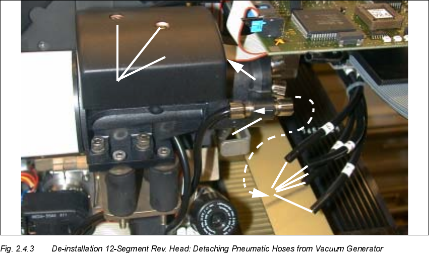
.H\
1. Compressed air feeder to the vacuum generator (5 hoses)
2. Collar on compressed air connection to the blast unit (support while pulling hoses off).
3. Cover over vacuum distributor board
(Fasteners: 2 socket hex head cap screws M2.5)
4. Ribbon cable: Connection on vacuum distributor board
Å Pull off the 5 compressed air hoses on the vacuum generator (see: Fig. 2.4.3).
Support in the case of the quick-release coupling (-> 2).
Å Remove the cover from the vacuum distributor board (loosen 2 socket hex head cap screws
M2.5, size 3).
Å Pull the 2 silicone hoses off the vacuum distributor board.
Å Pull the 2 silicone hoses off the silencer.
Å Support the placement head:
Undo the screws fastening the placement head: 3 socket hex head cap screws M4.
The head is still held in position by pins.
Å Pull the placement head (pins in the part to be pulled off) off the back part and set it down such
that it is not damaged, preferably in the proper package.