00192328-01.pdf - 第63页
SIPLACE S-25 HM 2 Retrofitt. Instruct. RV6-DLM1 Head & Nozzle Chang. RV6 Standa rd (Optionen) 02/01 Issue 2.4 Sequence: Ins talling the Hardware 61 Å Pu ll the ribbon c able "Il luminati on" off the d isman…
2 Retrofitt. Instruct. RV6-DLM1 Head & Nozzle Chang. RV6 Standard (Optionen) SIPLACE S-25 HM
2.4 Sequence: Installing the Hardware 02/01 Issue
60
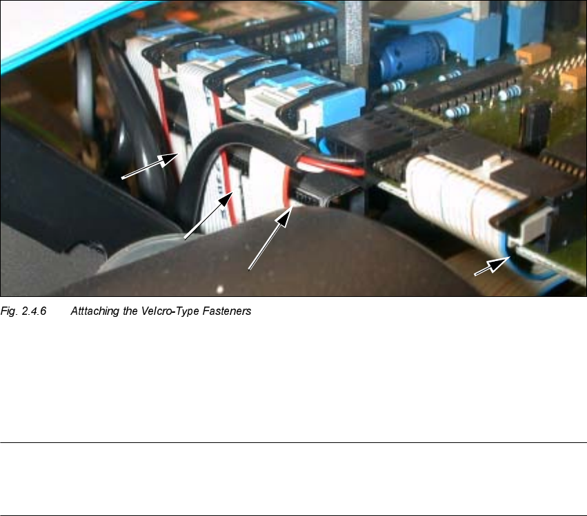
.H\
1. Velcro-type fastener under the ribbon cables (3 cables "Stepped motors")
2. Velcro-type fastener on the bottom "Conversion board, small axis" (cable "Vacuum board")
NOTE:
When the modular head board is installed, the strain relief devices remain MOUNTED on the jack
connectors of the new cables (which are on the new head).
Å ONLY when the "Conversion board, small axis" is present:
Remove the strain relief bows from ALL jack connectors on the ribbon cables of the NEW
placement head.
The new cables are held on each of the connectors of the conversion board by 2 black terminal
strips on the left and right (see: Fig. 2.4.7 -> 5).
Å Pull the 2 wide ribbon cables off the dismantled placement head and connect them to the new
6-segment revolver head:
Take note of: This cable is different for the modular head board than for the "Conversion board,
small axis".
Å Lay the two wide ribbon cables as shown in Fig. 2.4.1.
Å Make the plug-in connections on the board and placement head.
Å Secure the cables with the ribbon cable clamp (see: Fig. 2.4.1).

SIPLACE S-25 HM 2 Retrofitt. Instruct. RV6-DLM1 Head & Nozzle Chang. RV6 Standard (Optionen)
02/01 Issue 2.4 Sequence: Installing the Hardware
61
Å Pull the ribbon cable "Illumination" off the dismantled head and make the connection to the il-
lumination board and the new head. Take note of: This cable is different for the modular head
board than for the "Conversion board, small axis".
Å Make the connections of the 3 ribbon cables "Stepped motor" and the round cable "Revolver
head" (motor, tachometer) on the board.
Press the 3 ribbon cables with the 3 Velcro-type connections against the board holder.
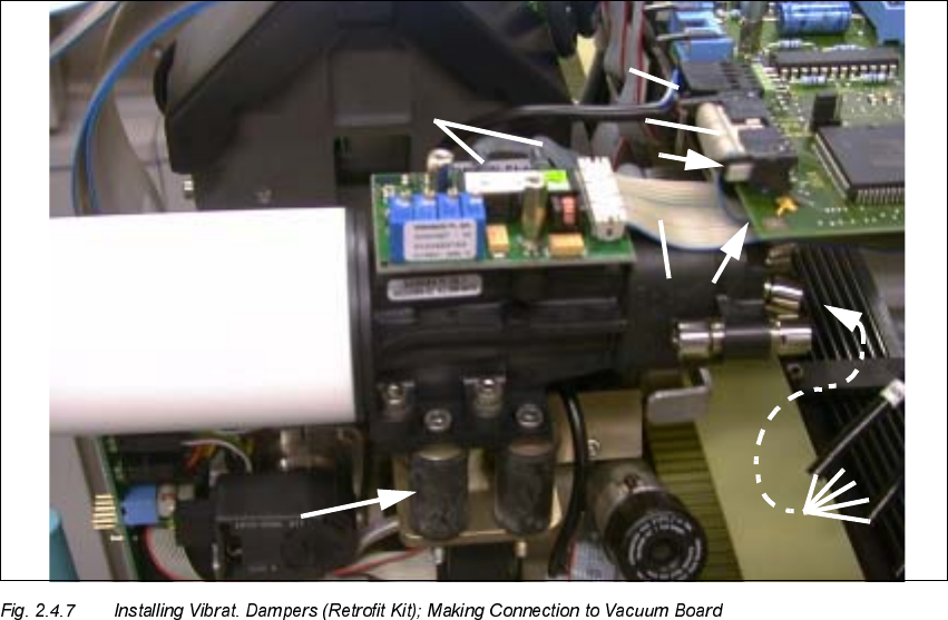
Å ,QVWDOOWKHQHZUXEEHUPHWDOYLEUDWLRQGDPSHUVIURPWKHUHWURILWNLWRQWKHQHZKHDG
VHH)LJ!DVGHVFULEHGLQGHWDLOLQWKH&RQYHUVLRQ,QVWUXFWLRQV
DLM1 Col-
lect&Place Head", Item-No. 00191684-03.
CAUTION
If, instead of the rubber-metal vibration dampers, a metal bracket is still installed on the remaining
RV12-DLM1 head, the bracket must be replaced by the dampers (from a 2 enclosed package).
De-install the vacuum generator incl. silencer and proceed as described in the conversion instruc-
tions (see above).
Å Place the vacuum generator incl. silencer on the adapter plate and screw it tight (4 washers
A 4.3 und 4 socket hex head cap screws M4; size 3, in the enclosed package).
The enclosed package contains all fastening parts.
Å If applicable, remove the cover from the vacuum generator (2 socket hex head cap screws
M2.5; size 2).
Å Connect the ribbon cable "Vacuum board" to the conversion board / modular head board.
Secure it to the bottom of the board with the Velcro-type fastener (see: Fig. 2.4.7 -> 2).
For details -> see conversion instructions for the DLM1 head.
Å Fold down all black terminal strips (see: Fig. 2.4.7 -> 5).
2 Retrofitt. Instruct. RV6-DLM1 Head & Nozzle Chang. RV6 Standard (Optionen) SIPLACE S-25 HM
2.4 Sequence: Installing the Hardware 02/01 Issue
62
.H\
1. 4 Rubber-metal vibration dampers (enclosed package from retrofit kit)
2. Velcro-type fastener (enclosed package from retrofit kit)
3. Ribbon cable "Vacuum board" (present on the new head)
4. Strain relief bow on the socket connector (removed for "Conversion board, small axis")
5. 2 terminal strips
6. Round cable "Revolver head" (tachometer, motor), present on new head
7. Pneumatic hoses, compressed air feed to the vacuum generator
8. Connection of the silicone hoses
Å Connect the 5 compressed air feeders - in correct order (number is on the hose) - to the vac-
uum generator and the blast unit (see: Fig. 2.4.7 -> 7).
Å Connect the sets of 2 thin silicone hoses to the vacumm board in the correct order (see: Fig.
2.4.7 -> 8).
Å Connect the 2 thick silicone hoses to the vacuum generator in the correct order.