00192328-01.pdf - 第70页
2 Retrofitt. Instruct. RV6-DLM1 Head & Nozzle Chang. RV6 Standard (Optionen) S IPLACE S-25 HM 2.4 Sequence: Inst alling the Hardware 02/01 Issue 68 Å Fasten the inte rface c able and t he com presse d air hos e as sh…
SIPLACE S-25 HM 2 Retrofitt. Instruct. RV6-DLM1 Head & Nozzle Chang. RV6 Standard (Optionen)
02/01 Issue 2.4 Sequence: Installing the Hardware
67
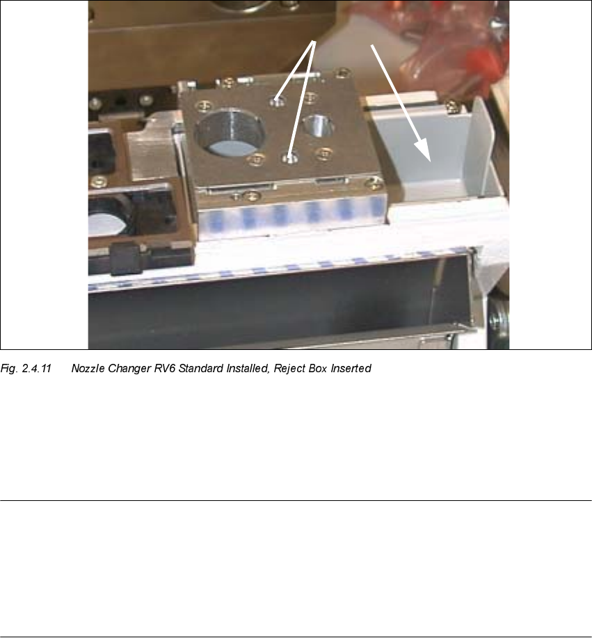
Å Remove the nozzle reject box and screw the nozzle changer on tight.
4 socket hex head cap screws M4 of different lengths, as follows:
– Back left -> M4 x 40
– Front left -> M4 x 50
– Back right -> M4 x 45
– Front right -> M4 x 10
.H\
1. Fiducials for position recognition
2. Reject box
NOTE:
In case of installing the RV6-DLM head during the upgrade S23 HM to SW V 502.xx, the bar from
the retrofit kit with the both fiducials for position recognition must always be mounted on the nozzle
changer RV12
, as described in the Retrofitting Instructions, Item no. 00192377-01
(position of the bar: see also in Fig. 2.4.8).
The fiducial marks are already on the new nozzle changer RV6.
Å Place the reject box from the nozzle changer back in.
2 Retrofitt. Instruct. RV6-DLM1 Head & Nozzle Chang. RV6 Standard (Optionen) SIPLACE S-25 HM
2.4 Sequence: Installing the Hardware 02/01 Issue
68
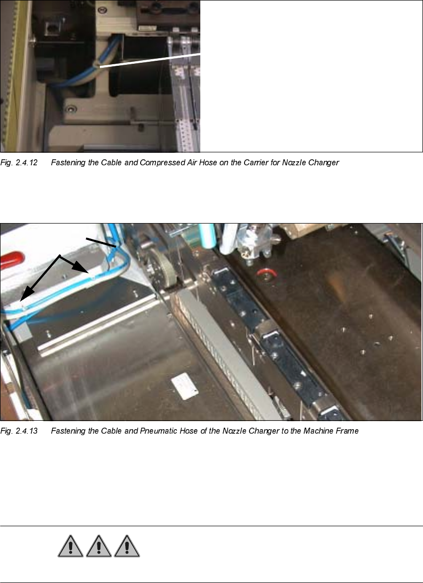
Å Fasten the interface cable and the compressed air hose as shown above.
.H\
3. 2 Mounting pedestals, adhesive, with cable tie
4. Cable tie
DANGER
Do not use alcohol for any cleaning work near open flame!
Cable tie
SIPLACE S-25 HM 2 Retrofitt. Instruct. RV6-DLM1 Head & Nozzle Chang. RV6 Standard (Optionen)
02/01 Issue 2.4 Sequence: Installing the Hardware
69
Å On the machine frame, degrease the area on which the 2 mounting pedestasl will be installed
(position, see: Fig. 2.4.11). Install the mounting pedestals.
Å Run the cable and the pneumatic hose and put on the cable ties (see: Fig. 2.4.11).
Å Remove all tools, etc., from the machine’s working area and close the doors of the machine
frame.