00197787-02_SI_SIPLACE_HeadVerification_EN.pdf - 第16页
3 Head verification principles 3.1 Starting the offline head verification 16 Software Manual SIPLACE Head Verification 03/2018 Checking the zero correction data of the star axis Fig.14: Zero correction data of star axis…
3 Head verification principles
3.1 Starting the offline head verification
Software Manual SIPLACE Head Verification 03/2018 15
3.1.3.3 Checking / modifying the zero point correction
The individual measurements of a head verification process are performed using the data that is
stored in the SIPLACEmachine configuration. In some cases, the data readout from the machine
does not match the machine data of the HCS. Therefore, it is recommended to check / modify the
data before running the head verification.
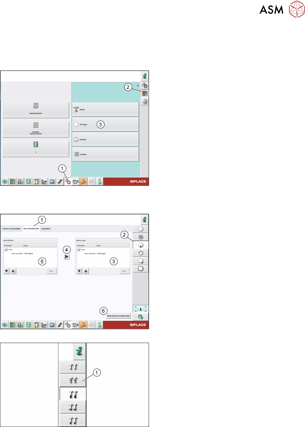
Fig.11: Check sensors and functions
► Click the Check sensors and functions icon(1).
► Click the Check sensors and functions of spe-
cific components icon(2).
► Open the head functions for the installed
head(3), for example, the CPP head.
Checking the zero correction data of the Z-axis
Fig.12: Zero correction data of Z-axis of C&P heads
For C&P heads, proceed as follows:
► Log on as machine service.
► Click the Check sensors and functions of Z-
axis icon(2).
► Click the Zero correction data tab(1).
► Compare the machine data(3) to the head
EPROM data(5).
► If the head EPROM data(5) is to be used, click
the arrow(4) to overwrite the machine data(3) or
click Edit… and enter the zero correction data.
► To save your settings, click the Write head and
machine data button(6).
Fig.13: Zero correction data of Z-axis of P&P modules
► For P&P modules, proceed as for C&P heads,
but note that the Check sensors and functions
of Z-axis icon(1) is different.
3 Head verification principles
3.1 Starting the offline head verification
16 Software Manual SIPLACE Head Verification 03/2018
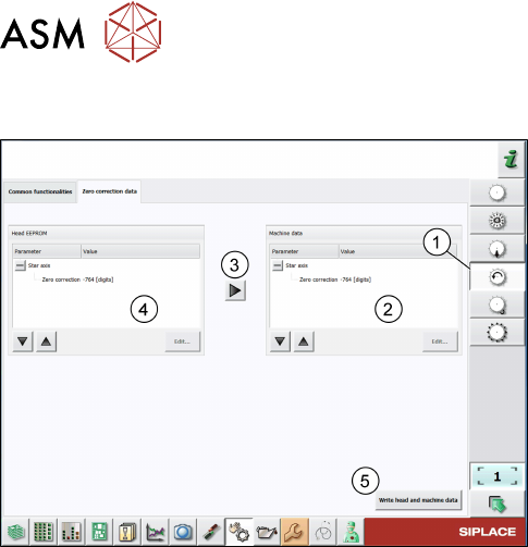
Checking the zero correction data of the star axis
Fig.14: Zero correction data of star axis of C&P heads
► Click the Check sensors and functions of star
axis icon(1).
► Click the Zero correction data tab.
► Compare the machine data(2) to the HCS
data(4).
► If the head EPROM data(2) is to be used, click
the arrow(3) to overwrite the machine data or
click Edit… and enter the zero correction data.
► To save your settings, click the Write head and
machine data button(5).
3 Head verification principles
3.2 Starting the online head verification
Software Manual SIPLACE Head Verification 03/2018 17
3.2 Starting the online head verification
NOTICE
Log in as „Machine service”
To enable the head verification functions, you need to be logged in Machine service.
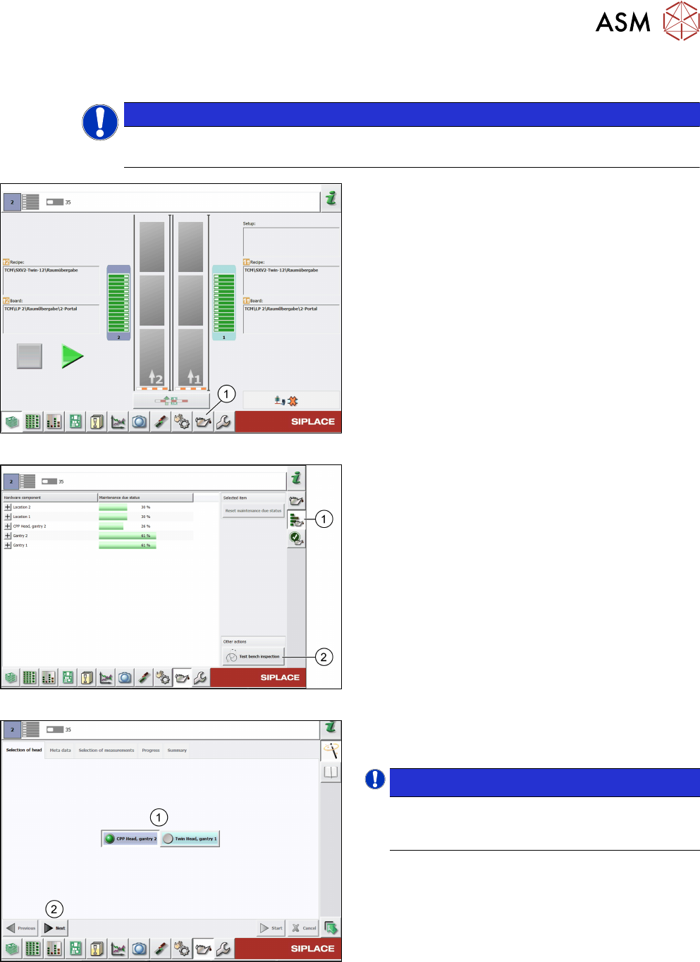
Fig.15: Test bench inspection icon selection
► Click the Display maintenance related views
icon(1) to start the head verification.
Fig.16: Maintenance status
► Click the Display maintenance status and stat-
istical data icon(1).
► Click the Test bench inspection button(2).
Fig.17: Head selection
► Select the head(1) to be verified.
► Click Next(2).
NOTICE!
The head verification supports only one head
(gantry) at a time. Parallel operation is not
supported.
.