00197787-02_SI_SIPLACE_HeadVerification_EN.pdf - 第37页
6 Description of the test results 6.2 Air & vacuum with head sensor Software Manual SIPLACE Head Verification 03/2018 37 6.2 Air & vacuum with head sensor 6.2.1 Measurement principle The Air & vacuum with hea…

6 Description of the test results
6.1 Air & vacuum checks
36 Software Manual SIPLACE Head Verification 03/2018
1 Results for the individual measurements
●
Vacuum values using the head sensor with the segment open and no nozzle at-
tached.
●
Vacuum values with the segment open and closed using the external sensor and a
517 nozzle attached.
●
Air blast values with the segment open and closed using the external sensor and a
517 nozzle attached.
●
Rise time determined how fast vacuum is built up.
●
Check of the vacuum sensor functionality.
2 Graph showing the rise time to max vacuum.
6.1.3 Interpretation of the results obtained
‘Vacuum head sensor’ OK / ‘Vacuum external sensor’ error
Cause Solution
Blockage in the vacuum circuit ► Check / exchange the tubes.
► Check / exchange the pneumatic rotary supply.
‘Vacuum head sensor’ error / ‘Vacuum external sensor’ OK
Cause Solution
Vacuum head sensor defective ► Replace the PRV.
6 Description of the test results
6.2 Air & vacuum with head sensor
Software Manual SIPLACE Head Verification 03/2018 37
6.2 Air & vacuum with head sensor
6.2.1 Measurement principle
The Air & vacuum with head sensors measurement is used to determine the vacuum and air
blast quality of the placement head and its segments. Several tests are performed to verify the dif-
ferent aspects of the vacuum system:
1. Test of the vacuum circuit in the placement position. The vacuum is measured twice, at first
with the segment open and the nozzle unblocked and then with the nozzle positioned at the
conveyor (endurance run unit). Both values are then compared to each other.
2. Test of the holding circuit with the nozzles unblocked.
3. Retest of the vacuum circuit in the placement position. The vacuum is measured for each seg-
ment with the calibration tool picked up in the top and bottom position.
4. Test of the air blast function.
6.2.2 Measurement result
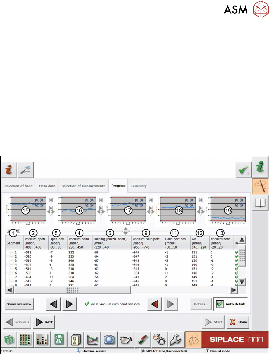
Fig.33: Result view – Air & vacuum with head sensors 1/2
6 Description of the test results
6.2 Air & vacuum with head sensor
38 Software Manual SIPLACE Head Verification 03/2018
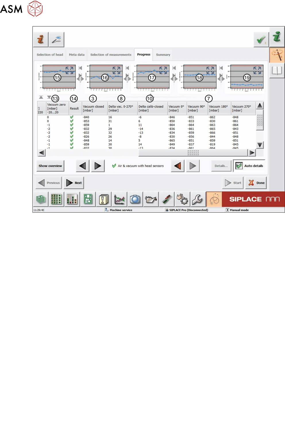
Fig.34: Result view – Air & vacuum with head sensors 2/2
See the legend below for details of both images:
1 Measured Segment
2 Values of the Vacuumopen measurement with open calibration nozzle.
3 Values of the Vacuumclosed measurement with the calibration nozzle touching the con-
veyor rail (endurance run unit).
4 Vacuum delta shows the difference between Vacuumopen and Vacuumclosed:
Vacuumdelta = Vacuumopen – Vacuumclosed
5 Open dev. shows the difference between Vacuum open of each segment and the Mean
Vacuum open:
Opendev. = Vacuumopen
n
– Vacuumopen
Median
6 Values of the Holdingcircuit measurement with open calibration nozzle.
7 Values of the Vacuum measurement at an angle of 0°, 90°, 180° and 270° with the cali-
bration tool picked up.
8 Delta vac. shows the difference between the smallest and the largest value of the Va-
cuum 0°, 90°, 180° and 270° measurements:
Deltavac. = Vacuum(0°, 90°, 180° 270°)
max
– Vacuum(0°, 90°, 180° 270°)
min
9 Values of the Vacuumcalibpart measurement with the calibration tool picked up.
10 Delta vac. shows the difference between Vacuumcalibpart and Vacuumclosed:
Deltacalib-closed = Vacuumcalibpart – Vacuumclosed
11 Calib part dev shows the difference Vacuum calib part of each segment and Mean Va-
cuum calib part.
Calib part dev = Vacuum calib part
n
– Vacuum calib part
Mean
.
12 Value of the Air blast measurement with an air blast of 200mbar applied to the segment.
13 Value of the Vacuumzero measurement with the air blast switched off.