00197787-02_SI_SIPLACE_HeadVerification_EN.pdf - 第38页
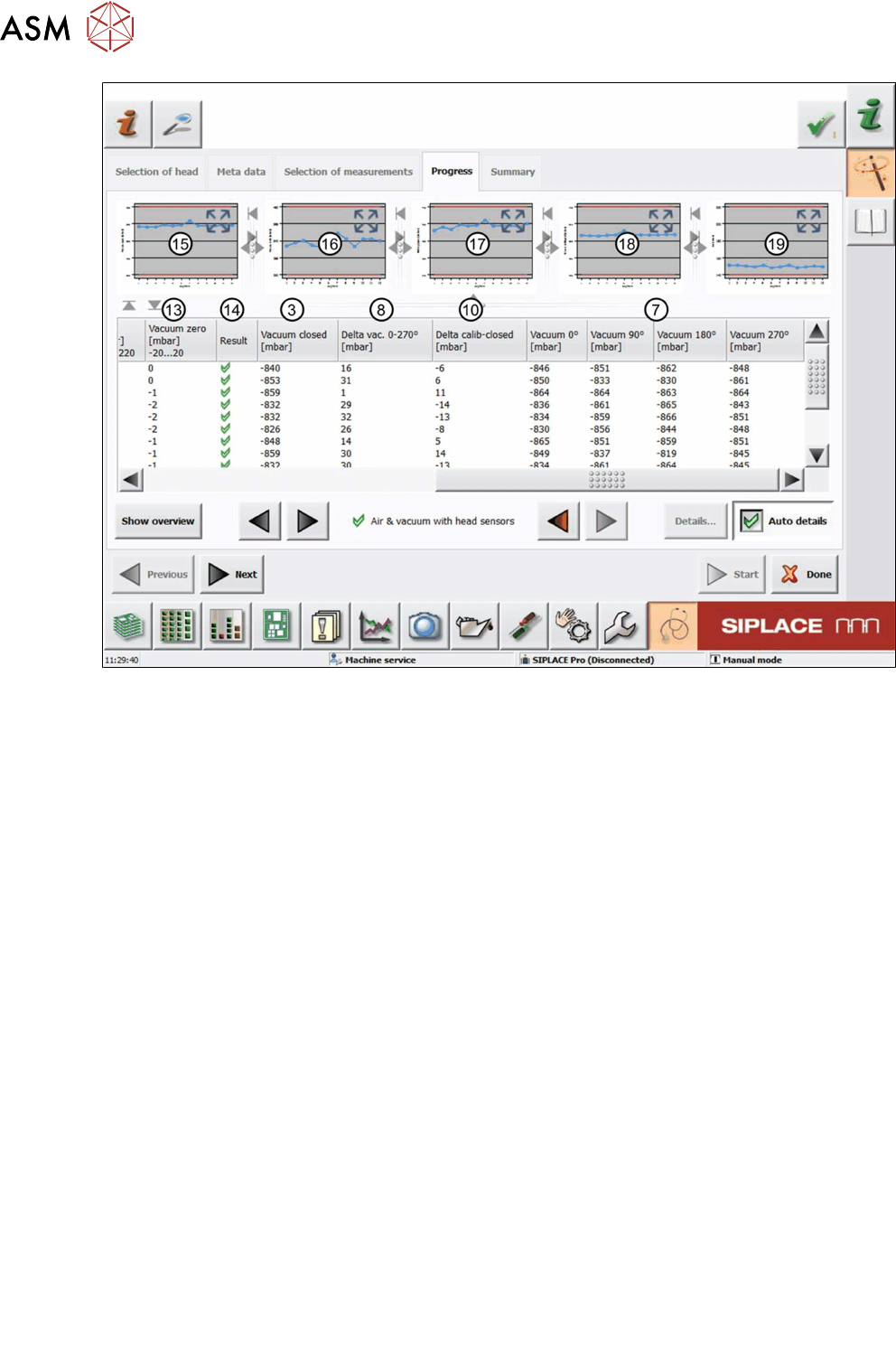
6 Description of the test results 6.2 Air & vacuum with head sensor 38 Software Manual SIPLACE Head Verification 03/2018 Fig.34: Result view – Air & vacuum with head sensors 2/2 See the legend below for details …
6 Description of the test results
6.2 Air & vacuum with head sensor
Software Manual SIPLACE Head Verification 03/2018 37
6.2 Air & vacuum with head sensor
6.2.1 Measurement principle
The Air & vacuum with head sensors measurement is used to determine the vacuum and air
blast quality of the placement head and its segments. Several tests are performed to verify the dif-
ferent aspects of the vacuum system:
1. Test of the vacuum circuit in the placement position. The vacuum is measured twice, at first
with the segment open and the nozzle unblocked and then with the nozzle positioned at the
conveyor (endurance run unit). Both values are then compared to each other.
2. Test of the holding circuit with the nozzles unblocked.
3. Retest of the vacuum circuit in the placement position. The vacuum is measured for each seg-
ment with the calibration tool picked up in the top and bottom position.
4. Test of the air blast function.
6.2.2 Measurement result
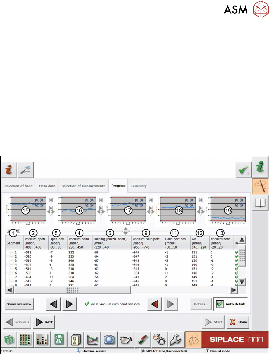
Fig.33: Result view – Air & vacuum with head sensors 1/2
6 Description of the test results
6.2 Air & vacuum with head sensor
38 Software Manual SIPLACE Head Verification 03/2018
Fig.34: Result view – Air & vacuum with head sensors 2/2
See the legend below for details of both images:
1 Measured Segment
2 Values of the Vacuumopen measurement with open calibration nozzle.
3 Values of the Vacuumclosed measurement with the calibration nozzle touching the con-
veyor rail (endurance run unit).
4 Vacuum delta shows the difference between Vacuumopen and Vacuumclosed:
Vacuumdelta = Vacuumopen – Vacuumclosed
5 Open dev. shows the difference between Vacuum open of each segment and the Mean
Vacuum open:
Opendev. = Vacuumopen
n
– Vacuumopen
Median
6 Values of the Holdingcircuit measurement with open calibration nozzle.
7 Values of the Vacuum measurement at an angle of 0°, 90°, 180° and 270° with the cali-
bration tool picked up.
8 Delta vac. shows the difference between the smallest and the largest value of the Va-
cuum 0°, 90°, 180° and 270° measurements:
Deltavac. = Vacuum(0°, 90°, 180° 270°)
max
– Vacuum(0°, 90°, 180° 270°)
min
9 Values of the Vacuumcalibpart measurement with the calibration tool picked up.
10 Delta vac. shows the difference between Vacuumcalibpart and Vacuumclosed:
Deltacalib-closed = Vacuumcalibpart – Vacuumclosed
11 Calib part dev shows the difference Vacuum calib part of each segment and Mean Va-
cuum calib part.
Calib part dev = Vacuum calib part
n
– Vacuum calib part
Mean
.
12 Value of the Air blast measurement with an air blast of 200mbar applied to the segment.
13 Value of the Vacuumzero measurement with the air blast switched off.

6 Description of the test results
6.2 Air & vacuum with head sensor
Software Manual SIPLACE Head Verification 03/2018 39
14 Result view indicating if the values are within (green tick) or outside (red cross) the limits.
15 Graph showing the Vacuumopen values for each segment.
16 Graph showing the Vacuumdelta values for each segment.
17 Graph showing the Holdingopen values for each segment.
18 Graph showing the Vacuumcalibpart values for each segment.
19 Graph showing the Air values for each segment.
6.2.3 Interpretation of the results obtained
‘Vacuum open’ / ‘Vacuum delta’ error for all segments
Cause Solution
Vacuum pump defective ► Maintain the vacuum pump or replace it.
Seal (four-hole rubber disk) for holding circuit
not fitted correctly or damaged
► Check the seal position or replace it.
Holding circuit polluted ► Maintain or clean the holding circuit in an
ultrasound bath.
‘Vacuum open’ / ‘Vacuum delta’ error for individual segments
Cause Solution
Filter disks sealing damaged / poor air-tightness
at the nozzle seating
► Replace the filter disks.
Nozzle worn or damaged ► Replace the nozzle.
Vacuum hose to the affected segment polluted
or damaged
► Replace the vacuum hose.
Holding circuit polluted ► Maintain or clean the holding circuit in an
ultrasound bath.
‘Delta vac. 0-270°’ error for individual segments
Cause Solution
Segment (DP) defective or without planarity to
the nozzle contact surface
► Replace the segment (DP).
Internal segment (DP) vacuum cycle defective ► Replace the segment (DP).