00197787-02_SI_SIPLACE_HeadVerification_EN.pdf - 第59页
6 Description of the test results 6.13 Force sensor calibration / Force sensor calibration (final) Software Manual SIPLACE Head Verification 03/2018 59 6.13.3 Interpretation of the results obtained ‘Sensor calibration’ a…
6 Description of the test results
6.13 Force sensor calibration / Force sensor calibration (final)
58 Software Manual SIPLACE Head Verification 03/2018
6.13 Force sensor calibration / Force sensor calibration (final)
6.13.1 Measurement principle
The Force sensor calibration serves as a preparatory step to ensure the force sensor is ready for
the subsequent force measurement.
The Force sensor calibration (final) is performed after the endurance run to verify the system re-
liability after being used for several cycles.
●
During the Sensor calibration, the Z-axis is moved down onto the force sensor several times
at 8 different angles to check if the force sensor is ready to use.
●
During the Spring preload measurement, the Z-axis is moved down onto the force sensor
several times at 8 different angles to check the mechanical position of the force sensor actu-
ator.
●
The Force 1N, Force 15N and DP positioning time measurement is used as a quick check
to verify the Sensor calibration and Spring preload measurement.
6.13.2 Measurement result
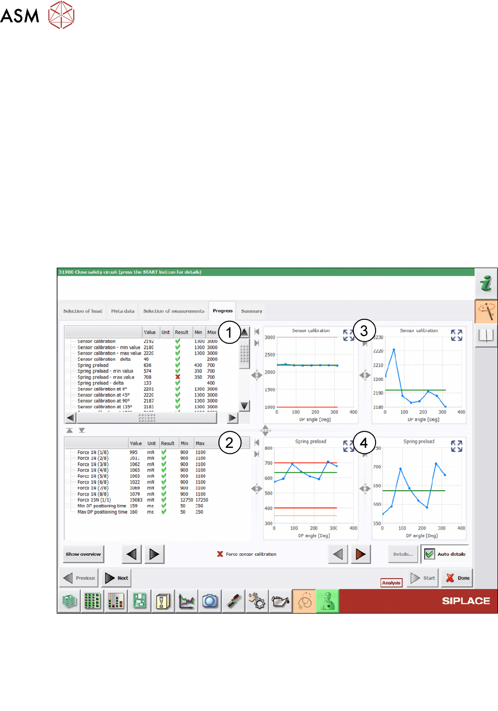
Fig.45: Result view - Force sensor calibration
1 Values determined for the Sensor calibration and Spring preload measurement.
2 Values determined for Force 1N, Force 15N and DP positioning time during the quick
check.
3 Graphs showing the Sensor calibration values for the tolerances allowed and in detail.
4 Graphs showing the Spring preload values for the tolerances allowed and in detail.

6 Description of the test results
6.13 Force sensor calibration / Force sensor calibration (final)
Software Manual SIPLACE Head Verification 03/2018 59
6.13.3 Interpretation of the results obtained
‘Sensor calibration’ and/or ‘Spring preload’ error
Cause Solution
Force measuring unit defective ► Adjust the force sensor unit (Q1/2018).
► Replace the force measuring and/or the trick and
feather unit (Q1/2018).
► Replace the P&P module.
► Send the P&P module to ASM for customer specific re-
pair.
6 Description of the test results
6.14 Head endurance run 01005
60 Software Manual SIPLACE Head Verification 03/2018
6.14 Head endurance run 01005
6.14.1 Measurement principle
The Head endurance run 01005 measurement checks the reliability of the Z-axis and the DPs, es-
pecially for small components, such as 0201 or 01005, which are typically processed using the
contactless placement function.
During the measurement of the Z-axis, each segment is moved up and down a number times to de-
termine the characteristics during the upward and downward movement. Before each downward
movement, the DP is turned by 180° with the time measured it takes to reach the final position.
6.14.2 Measurement result
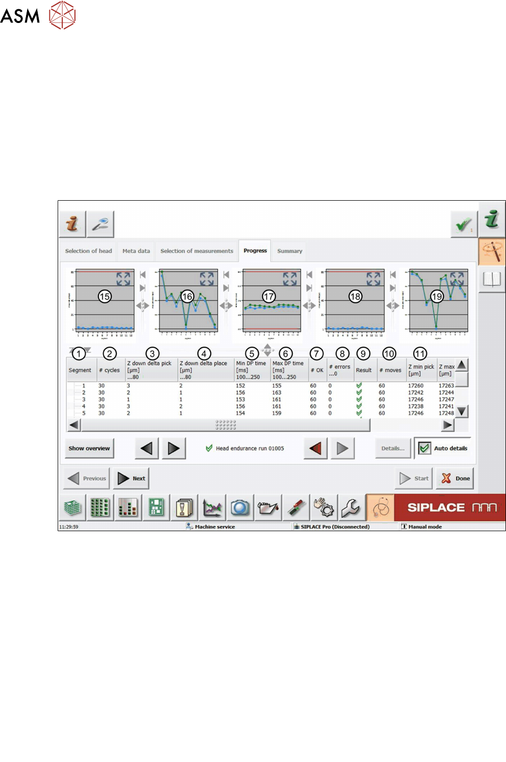
Fig.46: Result view – Head endurance run 01005 1/2
1 Measured Segment
2 Total number of cycles performed
3 Values from the difference between Zminpick and Zmaxpick:
Zdowndeltapick = Zmaxpick – Zminpick
4 Values from the difference between Zminplace and Zmaxplace:
Zdowndeltaplace = Zmaxplace – Zminplace
5 MinDPtime shows the value for the minimum time the DP needs to turn from 0° to 180°.
6 MaxDPtime shows the value for the maximum time the DP needs to turn from 180° to 0°.
7 #OK shows the number of successful Z-axis movements (up and down).
8 #errors…0 shows the number of failed Z-axis movements (up and down).
9 Result view indicating if the values are within (green tick) or outside (red cross) the limits.
10 #moves shows the number of performed Z-axis movements (in this case 30x down + 30x
up = 60).