00197787-02_SI_SIPLACE_HeadVerification_EN.pdf - 第57页
6 Description of the test results 6.12 Force measurement P&P module (TH) Software Manual SIPLACE Head Verification 03/2018 57 6.12.3 Interpretation of the results obtained ‘Force’ error Cause Solution Force sensor se…
6 Description of the test results
6.12 Force measurement P&P module (TH)
56 Software Manual SIPLACE Head Verification 03/2018
6.12 Force measurement P&P module (TH)
6.12.1 Measurement principle
During force measurement, the placement force is measured for the segment at several angles.
The following force measurements are available for P&P modules:
●
Force 1N (dynamic)
●
Force 2N (dynamic)
●
Force 5N (dynamic)
●
Force 10N (dynamic)
●
Force 15N (dynamic)
6.12.2 Measurement result
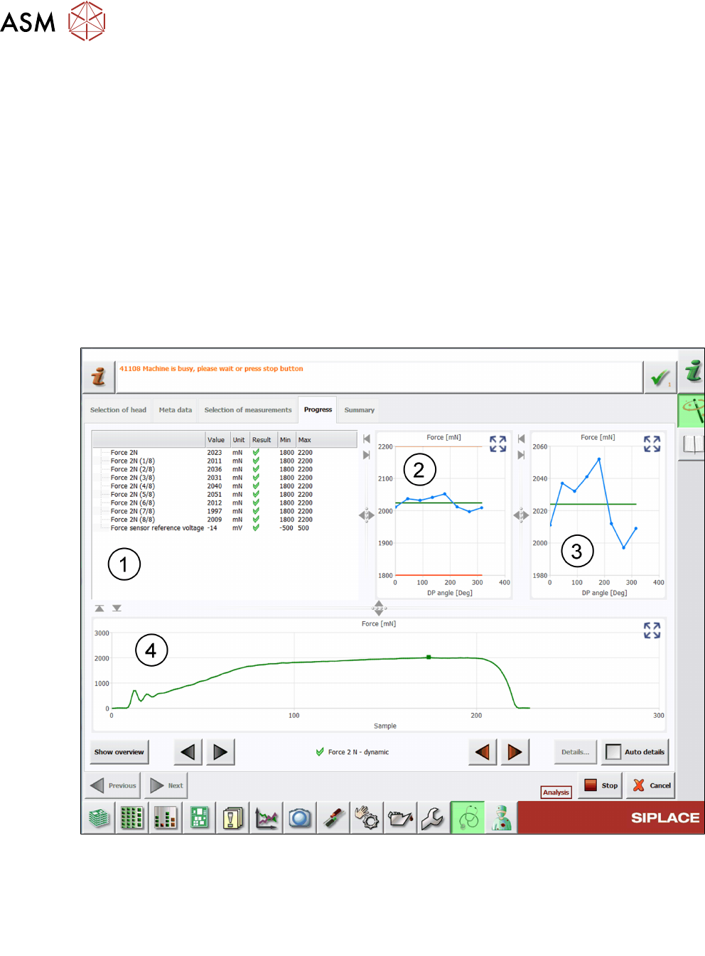
The following image shows an example of the Force2N(dynamic) measurement:
Fig.44: Result view – Force 2N (dynamic)
1 Table showing the Force measured at different angles.
2 Graph showing the Force measured at different angles and the limits specified.
3 Graph showing the Force measured at different angles in more detail.
4 Graph showing a sample of the Force measurement in detail.

6 Description of the test results
6.12 Force measurement P&P module (TH)
Software Manual SIPLACE Head Verification 03/2018 57
6.12.3 Interpretation of the results obtained
‘Force’ error
Cause Solution
Force sensor settings misaligned ► Adjust the spring force settings.
Force measuring unit defective ► Exchange the force measuring unit.
► Exchange / repair the P&P module.
Trick & feather unit defective ► Exchange the Trick & feather unit.
► Exchange / repair the P&P module.
6 Description of the test results
6.13 Force sensor calibration / Force sensor calibration (final)
58 Software Manual SIPLACE Head Verification 03/2018
6.13 Force sensor calibration / Force sensor calibration (final)
6.13.1 Measurement principle
The Force sensor calibration serves as a preparatory step to ensure the force sensor is ready for
the subsequent force measurement.
The Force sensor calibration (final) is performed after the endurance run to verify the system re-
liability after being used for several cycles.
●
During the Sensor calibration, the Z-axis is moved down onto the force sensor several times
at 8 different angles to check if the force sensor is ready to use.
●
During the Spring preload measurement, the Z-axis is moved down onto the force sensor
several times at 8 different angles to check the mechanical position of the force sensor actu-
ator.
●
The Force 1N, Force 15N and DP positioning time measurement is used as a quick check
to verify the Sensor calibration and Spring preload measurement.
6.13.2 Measurement result
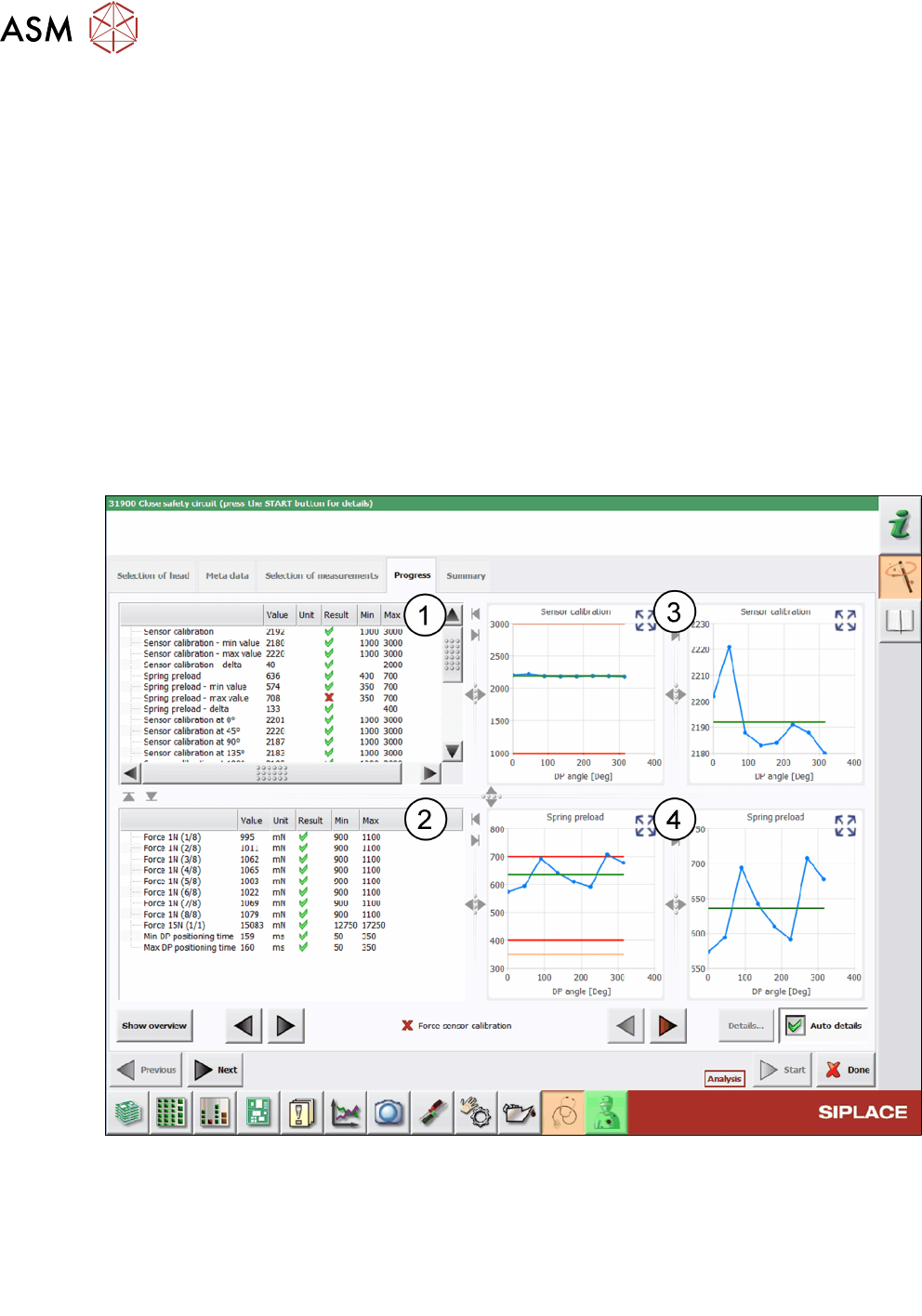
Fig.45: Result view - Force sensor calibration
1 Values determined for the Sensor calibration and Spring preload measurement.
2 Values determined for Force 1N, Force 15N and DP positioning time during the quick
check.
3 Graphs showing the Sensor calibration values for the tolerances allowed and in detail.
4 Graphs showing the Spring preload values for the tolerances allowed and in detail.