00197787-02_SI_SIPLACE_HeadVerification_EN.pdf - 第47页
6 Description of the test results 6.7 DP positioning time Software Manual SIPLACE Head Verification 03/2018 47 6.7 DP positioning time 6.7.1 Measurement principle The DP positioning time is used to verify the encoder dis…
6 Description of the test results
6.6 Component sensor calibration
46 Software Manual SIPLACE Head Verification 03/2018
6.6 Component sensor calibration
6.6.1 Measurement principle
The Component sensor calibration measurement checks the degree to which the Z height of the
nozzle changes when the Z-axis is moved downwards in the ‘axes overlapping’ mode, during the
star rotation and when the component sensor is triggered. When the component sensor switches,
the measurement checks whether the front surface of the nozzle tip triggers the component sensor
eccentrically when the axes overlap. The corner of the front nozzle surface moves slightly down-
wards during a rotation around the star in the lower angles (as in the case of jaw stop left and jaw
stop right). This can also be described as a diagonal tilting effect. This Z-axis change is recorded
during this measurement at the component sensor.
6.6.2 Measurement result
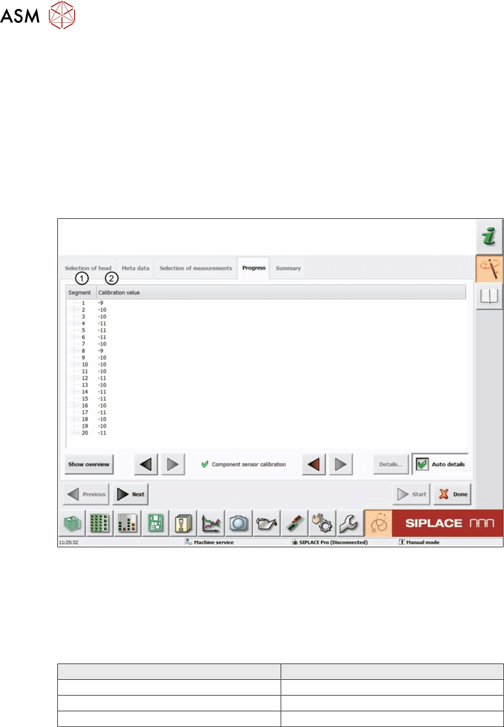
Fig.38: Result view – Component sensor calibration
1 Measured Segment
2 Calibration value calculated from the change in the Z-axis travel path in axes overlapping
mode (star axis to Z-axis) until the component sensor is triggered.
6.6.3 Interpretation of the results obtained
‘Calibration value’ error for all segments
Cause Solution
Component sensor fitted at a slant ► Readjust the component sensor.
Component sensor lens defective ► Replace the component sensor.
Component sensor lens dirty ► Clean the sensor with isopropyl alcohol.
‘Calibration value’ error for individual segments
► Check the nozzles.
6 Description of the test results
6.7 DP positioning time
Software Manual SIPLACE Head Verification 03/2018 47
6.7 DP positioning time
6.7.1 Measurement principle
The DP positioning time is used to verify the encoder disk and read head of the TH D-Axis.
The test is split up in two sections:
●
Firstly, the D-axis is positioned forwards and backwards by 90° steps 40 times. For each step,
the time is measured it takes the axis to reach the position.
●
Secondly, the sequence is repeated using 90° steps.
6.7.2 Measurement result
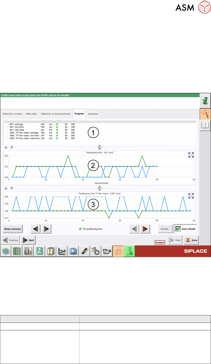
Fig.39: Result view - DP positioning time
1 Minimum, maximum and average time determined when stepping the axis by 90° / 180°.
2 Graph showing the DP positioning by 90° steps.
3 Graph showing the DP positioning by 180° steps.
6.7.3 Interpretation of the results obtained
‘DP positioning time’ error
Cause Solution
Encoder disk or read polluted ► Clean the encoder disk / read head (Q1/2018).
Encoder disk or read defective ► Replace the ‘Trick a. feather unit/P+P module
(Q1/2018)’.
► Replace the P&P module.
► Send the P&P module to ASM for customer specific re-
pair.
6 Description of the test results
6.8 DP rotation test
48 Software Manual SIPLACE Head Verification 03/2018
6.8 DP rotation test
6.8.1 Measurement principle
The DP rotation measurement is used to verify the DP position.
During the measurement, the calibration tool is picked up, moved to the component camera and
positioned at 4°(4000 digits). The component camera then captures a live image of the calibration
tool and checks if the position is within the allowed limits.
6.8.2 Measurement result
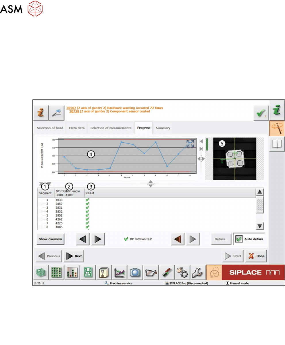
Fig.40: Result view – DP rotation test
1 Measured Segment
2 DP rotation angle of the calibration tool determined by the component camera.
3 Result view indicating if the values are within (green tick) or outside (red cross) the limits.
4 Graph showing the measured DP rotation angle for each segment.
5 Live image of the calibration tool.