00197787-02_SI_SIPLACE_HeadVerification_EN.pdf - 第69页
6 Description of the test results 6.17 Holding circuit (sealed nozzles) Software Manual SIPLACE Head Verification 03/2018 69 6.17.3 Interpretation of the results obtained ‘Holding circuit (sealed nozzles)’ error for all …
6 Description of the test results
6.17 Holding circuit (sealed nozzles)
68 Software Manual SIPLACE Head Verification 03/2018
6.17 Holding circuit (sealed nozzles)
6.17.1 Measurement principle
After referencing the star, vacuum is applied to the segments in the holding circuit and the vacuum
value of each segment is measured. Using sealed nozzles simulates the condition of a picked-up
component.
6.17.2 Measurement result
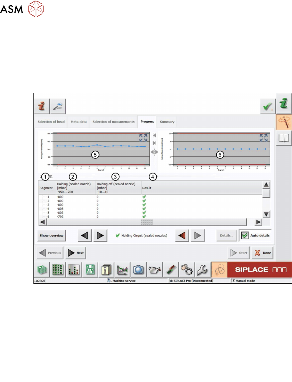
Fig.51: Result view – Holding circuit (sealed nozzles) measurement
1 Measured Segment
2 Values of the Holding(sealed nozzles) measurement with sealed nozzles
3 Values of the Holdingoff(sealed nozzles) measurement show how fast the vacuum is
reduced after it is switched off.
In an ideal case, the measured value is 0mbar (atmospheric pressure).
4 Result view indicating if the values are within (green tick) or outside (red cross) the limits.
5 Graph showing the Holding (sealed nozzles) values for each segment with vacuum en-
abled.
6 Graph showing the Holding off (sealed nozzles) values for each segment after the va-
cuum has been disabled.
6 Description of the test results
6.17 Holding circuit (sealed nozzles)
Software Manual SIPLACE Head Verification 03/2018 69
6.17.3 Interpretation of the results obtained
‘Holding circuit (sealed nozzles)’ error for all segments
Cause Solution
Vacuum supply defective ► Check the air hoses.
► Check and maintain the vacuum pump if
applicable.
Vacuum block of CPP defective ► Replace the CPP vacuum block with a new
one.
Leaky O-ring between vacuum unit and silencer ► Check the O-ring assembly or replace it.
Seal for holding circuit / aperture ring incorrectly
fitted or damaged
► Check the seal position and replace it if
necessary.
‘Holding circuit (sealed nozzles)’ error for individual segments
Cause Solution
Filter disk damaged or incorrectly fitted ► Replace the filter disk with a new one.
Vacuum hose for segment damaged or dirty ► Clean the vacuum hose and replace it if
necessary.
Holding circuit unit polluted ► Clean the holding circuit unit in an ultra-
sonic bath.
Leaky vacuum nozzle ► Replace the vacuum nozzle with a new
one.
‘Holding circuit (sealed nozzles)’ error for more than one segment
Cause Solution
Holding circuit unit polluted ► Clean the holding circuit unit in an ultra-
sonic bath.
Seal for holding circuit / aperture ring incorrectly
fitted or damaged
► Check the seal position and replace it if
necessary.
6 Description of the test results
6.18 Nozzle spring
70 Software Manual SIPLACE Head Verification 03/2018
6.18 Nozzle spring
6.18.1 Measurement principle
The Nozzle spring measurement checks the state of the spring with respect to its deflection, brit-
tleness and the switching (signal) threshold at the Z-axis down light barrier.
Before the measurement starts, a head reference run is carried out during which all nozzles are
pressed onto the DP at the nozzle station to ensure a firm fitting. During the measurement itself,
every segment is moved down and back up again using different travel profiles to measure the pos-
itions at which the end signal is triggered.
●
The nozzle spring is verified by comparing the positions at which the end signal is triggered,
moving the segment down first with low force and the current sensor mode (Z-Low Force), fol-
lowed by high force and light barrier mode (Z-High Force).
●
The threshold value is verified by comparing the position at which the end signal is triggered,
moving the segment down with standard force and light barrier mode (Z-Light Barrier), with
the position determined for the low force movement (Z-Low Force).
6.18.2 Measurement result
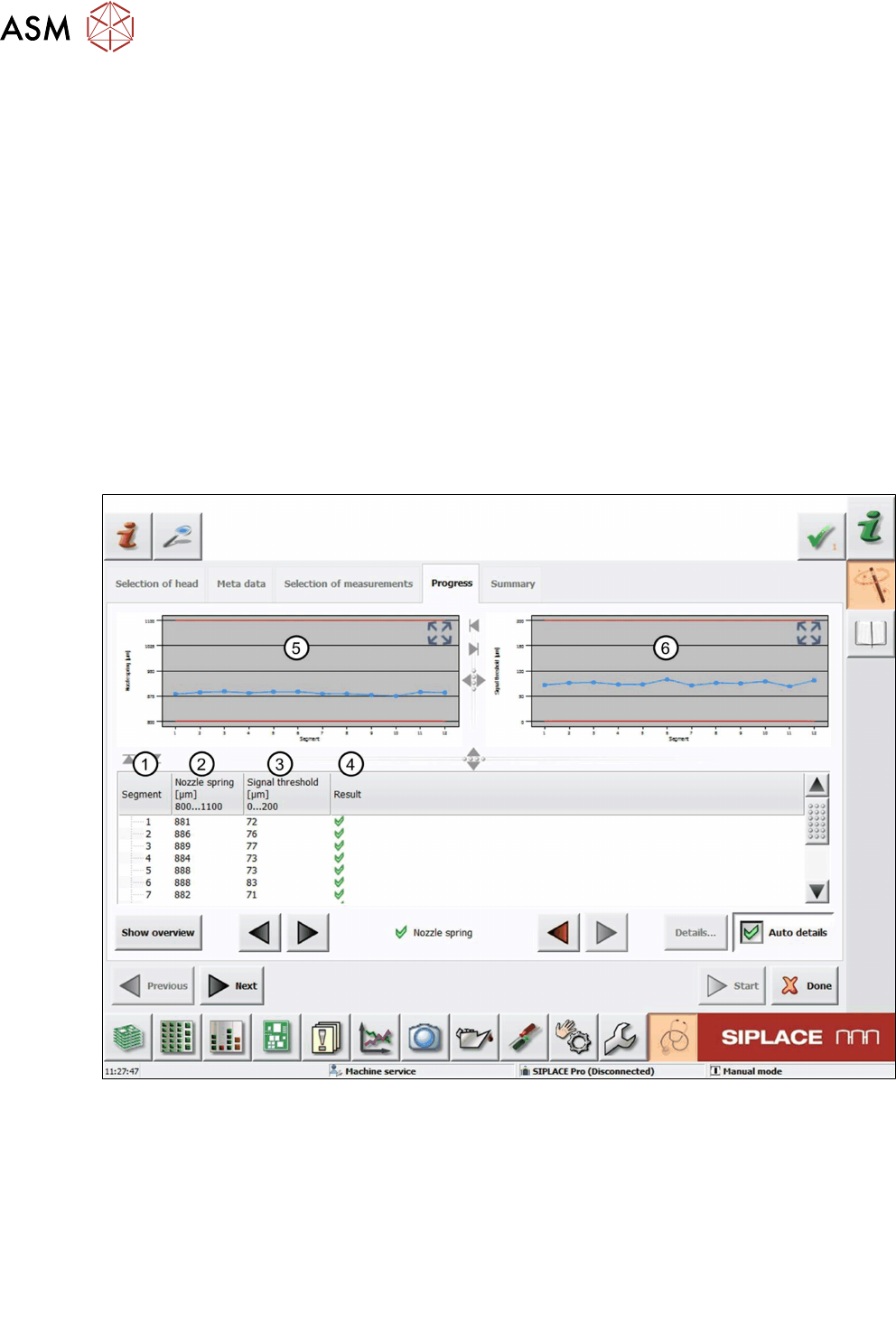
Fig.52: Result view – Nozzle spring measurement
1 Measured Segment
2 Calculated value for the spring that has been compressed completely:
Nozzlespring = Z-HighForce – Z-LowForce
3 Calculated value for the distance until the Z-axis down light barrier is triggered.
Signal threshold = Z-Light Barrier - Z-Low Force
4 Result view indicating if the values are within (green tick) or outside (red cross) the limits.
5 Graph showing the Nozzle spring values for each segment.
6 Graph showing the Signal threshold values for each segment.