00197787-02_SI_SIPLACE_HeadVerification_EN.pdf - 第17页
3 Head verification principles 3.2 Starting the online head verification Software Manual SIPLACE Head Verification 03/2018 17 3.2 Starting the online head verification NOTICE Log in as „Machine service” To enable the hea…
3 Head verification principles
3.1 Starting the offline head verification
16 Software Manual SIPLACE Head Verification 03/2018
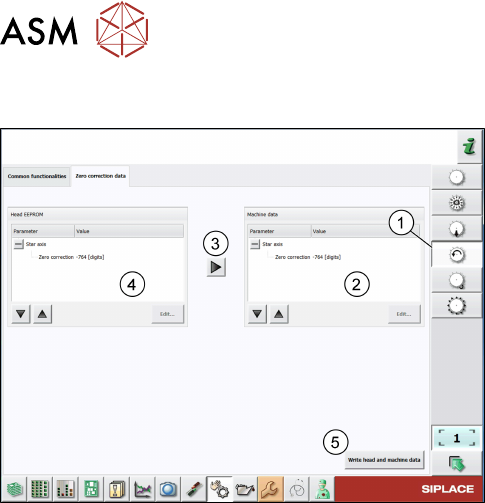
Checking the zero correction data of the star axis
Fig.14: Zero correction data of star axis of C&P heads
► Click the Check sensors and functions of star
axis icon(1).
► Click the Zero correction data tab.
► Compare the machine data(2) to the HCS
data(4).
► If the head EPROM data(2) is to be used, click
the arrow(3) to overwrite the machine data or
click Edit… and enter the zero correction data.
► To save your settings, click the Write head and
machine data button(5).
3 Head verification principles
3.2 Starting the online head verification
Software Manual SIPLACE Head Verification 03/2018 17
3.2 Starting the online head verification
NOTICE
Log in as „Machine service”
To enable the head verification functions, you need to be logged in Machine service.
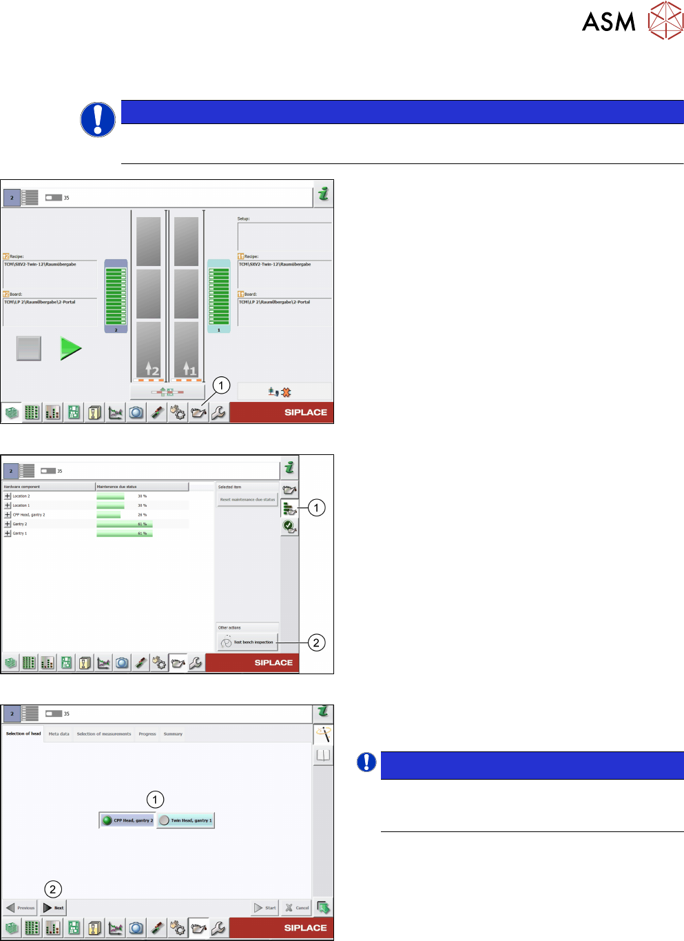
Fig.15: Test bench inspection icon selection
► Click the Display maintenance related views
icon(1) to start the head verification.
Fig.16: Maintenance status
► Click the Display maintenance status and stat-
istical data icon(1).
► Click the Test bench inspection button(2).
Fig.17: Head selection
► Select the head(1) to be verified.
► Click Next(2).
NOTICE!
The head verification supports only one head
(gantry) at a time. Parallel operation is not
supported.
.
3 Head verification principles
3.3 Head verification software
18 Software Manual SIPLACE Head Verification 03/2018
3.3 Head verification software
3.3.1 Meta data
Meta data are required to identify the verified head and the person who performed the verification.
All entered data are shown in the protocol that is generated when the head verification is finished.
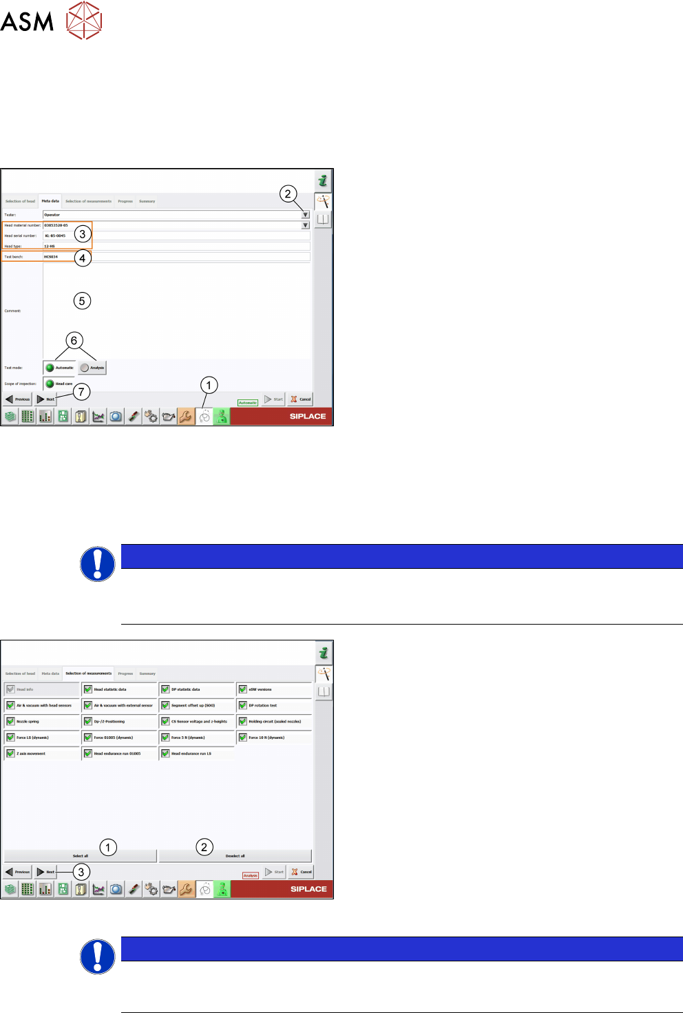
Fig.18: Meta data tab
► Click the Test bench inspection icon(1).
► Enter or select(2) the person performing the veri-
fication.
► All head information(3) is read out from the head
EPROM. Verify if the Head material number
corresponds to the information written on the
head label and modify it if applicable.
► The Test bench ID(4) is entered during the in-
stallation of the HCS software. For information on
how to modify the Test Bench ID, see 3.1.3.2
"Modifying the test bench configuration" [}14].
► Enter a comment(5), if necessary.
► Select the Test mode(6) to be used:
- Automatic: All tests must be performed.
- Analyze: Individual tests to be performed can
be configured.
► Click Next(7).
3.3.2 Selection of measurements
The Selection of measurements tab shows all tests that are available for the head to be verified.
NOTICE
Selection of measurements
Tests can only be selected in the Analysis mode and are indicated by a green tick. In the
Automatic mode, all tests are preselected and greyed out.
Fig.19: Selection of measurements tab – Analysis mode
► Manually select and/or deselect tests. You can
also click the Select all(1) button to select all
tests at once or click the Deselect all(2) button
to deselect all tests at once.
► Click Next(3).
NOTICE
To gain a reliable overview about the head condition, it is recommended to run a full head
verification including all available tests. The order in which the tests are performed is line-
wise starting from the top left test to the bottom right test.