00197787-02_SI_SIPLACE_HeadVerification_EN.pdf - 第29页
5 Online head verification workflow 5.1 Preliminary steps Software Manual SIPLACE Head Verification 03/2018 29 5 Online head verification workflow 5.1 Preliminary steps Preparatory tasks If the head verification is perfo…

4 Offline head verification
4.5 Available measurements for TH
28 Software Manual SIPLACE Head Verification 03/2018

5 Online head verification workflow
5.1 Preliminary steps
Software Manual SIPLACE Head Verification 03/2018 29
5 Online head verification workflow
5.1 Preliminary steps
Preparatory tasks
If the head verification is performed systematically in your production environment, it is recommen-
ded to prepare complete magazines with the required nozzle types to reduce the time that is re-
quired to change the nozzle changer configuration.
Vacuum pump operation
The following notes apply primarily to heads of type C&P20x as the standard configuration of this
head is set up for the vacuum pump operation:
NOTICE
Influence from 2
nd
gantry
On machines equipped with a vacuum pump, the vacuum is no longer generated for the in-
dividual head but for the whole placement area instead. For the head verification process, it
is crucial to eliminate any influence from the gantry or head which is currently not verified.
If the head verification is to be performed in a placement area where a vacuum pump is
used to generate the vacuum, one of the following nozzle configurations is recommended
for the heads which are not to be verified:
► Closed red vacuum nozzles to close off the vacuum system (preferred solution)
► Nozzles with small cross-section, e.g. 4104 or 4105 (acceptable solution due to small
opening)
NOTICE
Disabled segments not verified
If segments have been disabled, these segments are omitted from the head verification
process. No measurement will be performed for these segments. However, an error will be
shown for each omitted segment, indicated by a red cross, as the measurements are miss-
ing.
Segment 1 cannot be disabled, as this is required for the general functioning of the head.
5 Online head verification workflow
5.2 Available measurements for C&P20A
30 Software Manual SIPLACE Head Verification 03/2018
5.2 Available measurements for C&P20A
Required tools
●
1x calibration jig version SST23 [03034148-xx]
●
20x Nozzle 1235 [03015222-xx]
●
20x Nozzle 1069 [03094112-xx]
Verification workflow
NOTICE
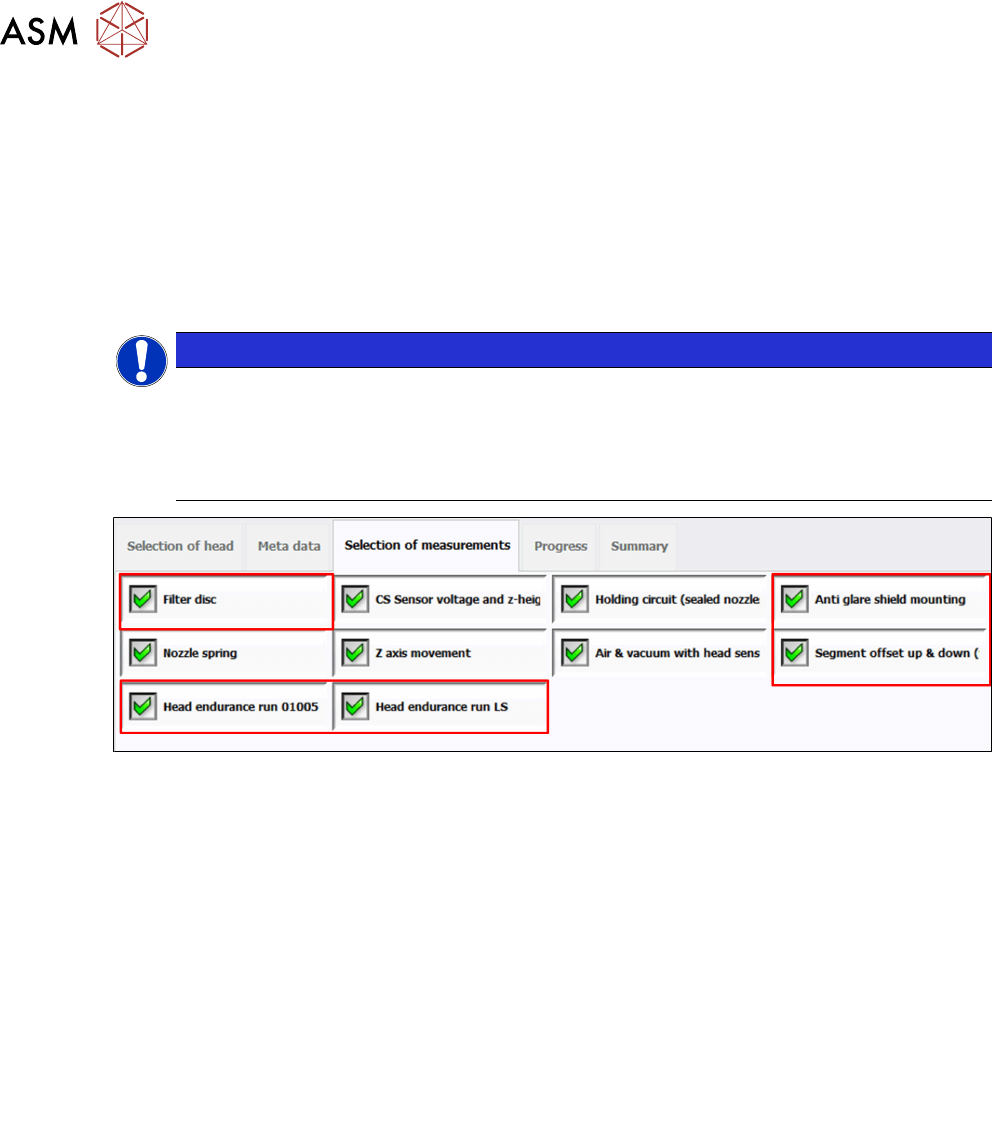
Head Verification versus Test Bench Inspection mode
The Head Verification mode provides a fast verification with the main focus on the Z-axis
and the vacuum system. All red framed tasks are not shown.
The Test Bench Inspection mode includes all available tasks as shown in figure "Available
measurements for C&P20A (Test Bench Inspection mode)" [}30].
Fig.28: Available measurements for C&P20A (Test Bench Inspection mode)
1 Filter disc
See 6.10 "Filter Disc" [}52]
2 CS Sensor voltage and z-heights
See 6.5 "CS Sensor voltage and z-heights" [}44]
3 Holding circuit (sealed nozzles)
See 6.17 "Holding circuit (sealed nozzles)" [}68]
4 Anti-glare shield mounting
See 6.4 "Anti-glare shield mounting" [}42]
5 Nozzle spring
See 6.18 "Nozzle spring" [}70]
6 Z-axis movement
See 6.22 "Z-axis movement" [}81]
7 Air & vacuum with head sensors
See 6.2 "Air & vacuum with head sensor" [}37]
8 Segment offset up & down (fast)
See 6.19 "Segment offset up & down (fast)" [}72]
9 Head Endurance Run 01005
See 6.14 "Head endurance run 01005" [}60]
10 Head Endurance Run LS
See 6.16 "Head endurance run LS" [}65]