3MAINTENANCE__O.pdf - 第102页
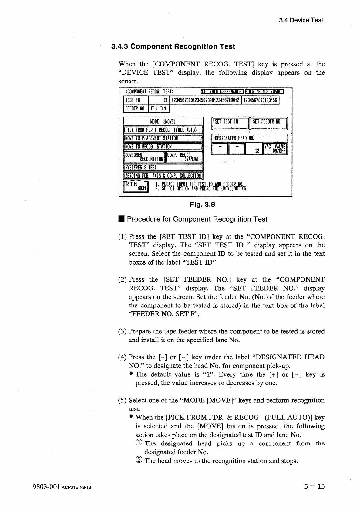
3.4 Device Test 3.4 . 3 Component Recognition Test When the [ COMPONENT RECOG . TEST ] key is pressed at the “ DEVICE TEST ” display , the following display appears screen . the on ( ) . llKf / ^ NARi 1 HUt S . / P ( Atf…
3.4
Device
Test
•
OK
Result
of
Recognition
The
X
/
Y
table
moves
to
the
place
where
a
fiducial
mark
is
located
at
the
camera
center
and
the
outline
of
the
mark
shape
and
crosslines
are
displayed
.
The
positional
deviation
(
X
and
Y
)
of
the
fiducial
mark
from
the
camera
center
is
displayed
in
the
©
-
marked
area
of
the
window
.
Note
:
The
displayed
positional
deviation
shows
the
deviation
detected
before
testing
.
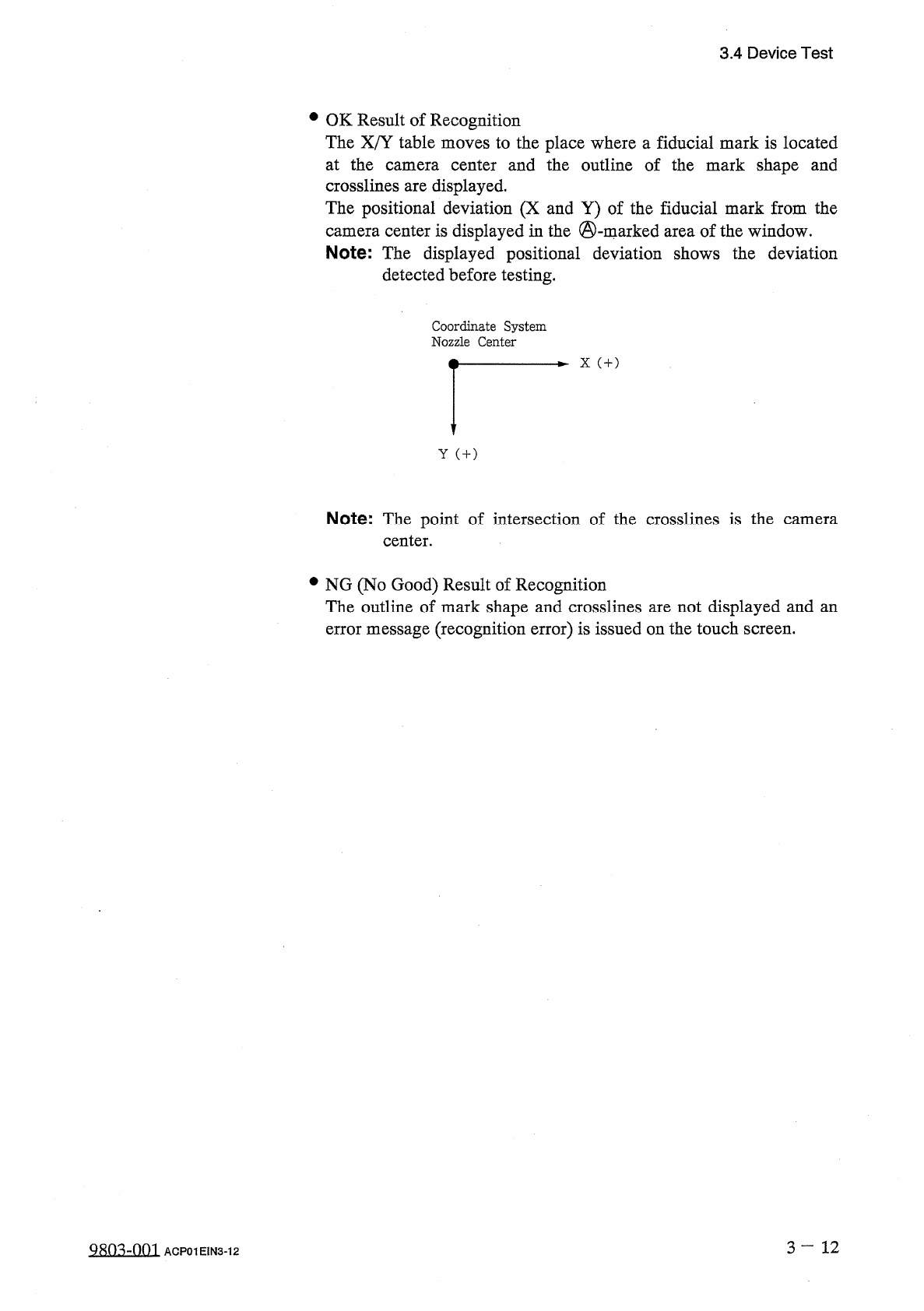
Coordinate
System
Nozzle
Center
X
(
+
)
Y
(
+
)
Note
:
The
point
of
intersection
of
the
crosslines
is
the
center
.
camera
•
NG
(
No
Good
)
Result
of
Recognition
The
outline
of
mark
shape
and
crosslines
are
not
displayed
and
an
error
message
(
recognition
error
)
is
issued
on
the
touch
screen
.
3
—
12
Q
^
-
001
ACP
01
EIN
3
-
12
3.4
Device
Test
3.4
.
3
Component
Recognition
Test
When
the
[
COMPONENT
RECOG
.
TEST
]
key
is
pressed
at
the
“
DEVICE
TEST
”
display
,
the
following
display
appears
screen
.
the
on
(
)
.
llKf
/
^
NARi
1
HUt
S
.
/
P
(
Atf
/
iM
~
l
〈
COMPONENT
RECOG
.
TEST
〉
12345678901234567890123456
^
901
^
1
123456789
Q
1234
S
61
TEST
[
0
8
FEEDER
NO
.
FI
01
1
MODE
[
MOVE
!
SET
TEST
ID
SET
FEEDER
HO
.
PICK
FROM
FPU
RECTO
.
(
FULL
AUTO
)
:
;
fESiSNATED
HEAD
NO
,
m
i
2
RI
MOVE
TO
PLACEMENT
HAtlOH
MOVE
TO
gECOG
.
STATION
"
ICOGNITION
CWP
-
REfcL
)
C
0
MP
0
HYSTERESIS
TEST
ZEROING
FDR
.
AXIS
l
CQKP
.
COLLECTION
FTN
^
■
膽
_
麵
5
_
1
.
Fig
.
3.8
■
Procedure
for
Component
Recognition
Test
(
1
)
Press
the
[
SET
TEST
ID
]
key
at
the
“
COMPONENT
RECOG
.
TEST
”
display
.
The
“
SET
TEST
ID
”
display
appears
on
the
screen
.
Select
the
component
ID
to
be
tested
and
set
it
in
the
text
boxes
of
the
label
“
TEST
ID
”
.
(
2
)
Press
the
[
SET
FEEDER
NO
.
]
key
at
the
“
COMPONENT
RECOG
.
TEST
”
display
.
The
“
SET
FEEDER
NO
.
”
display
appears
on
the
screen
.
Set
the
feeder
No
.
(
No
.
of
the
feeder
where
the
component
to
be
tested
is
stored
)
in
the
text
box
of
the
label
“
FEEDER
NO
.
SET
F
”
.
(
3
)
Prepare
the
tape
feeder
where
the
component
to
be
tested
is
stored
and
install
it
on
the
specified
lane
No
.
(
4
)
Press
the
[
+
]
or
[
~
]
key
under
the
label
“
DESIGNATED
HEAD
NO
.
”
to
designate
the
head
No
.
for
component
pick
-
up
.
•
The
default
value
is
“
1
”
.
Every
time
the
[
+
]
or
[
-
]
key
is
pressed
,
the
value
increases
or
decreases
by
one
.
(
5
)
Select
one
of
the
“
MODE
[
MOVE
]
”
keys
and
perform
recognition
test
.
•
•
When
the
[
PICK
FROM
FDR
.
&
RECOG
.
(
FULL
AUTO
)
]
key
is
selected
and
the
[
MOVE
]
button
is
pressed
,
the
following
action
takes
place
on
the
designated
test
ID
and
lane
No
.
①
The
designated
head
picks
up
a
component
from
the
designated
feeder
No
.
②
The
head
moves
to
the
recognition
station
and
stops
.
3
—
13
Q
8
Q
^
-
0
m
ACP
01
EIN
3
-
13
3.4
Device
Test
③
Component
recognition
function
is
implemented
.
Note
:
The
[
PAUSE
]
button
is
valid
during
the
above
-
described
operation
.
•
When
the
[
MOVE
TO
PLACEMENT
STATION
]
key
is
selected
and
the
[
MOVE
]
button
is
pressed
,
the
following
action
takes
place
.
①
The
vacuum
nozzle
on
the
specified
head
No
.
moves
to
the
pick
-
up
position
and
stops
.
Let
the
nozzle
pick
up
a
component
by
hand
.
•
When
the
[
MOVE
TO
RECOG
.
STATION
]
key
is
selected
and
the
[
MOVE
]
button
is
pressed
,
the
following
action
takes
place
.
②
The
head
which
picked
up
a
component
recognition
station
and
stops
.
Note
:
This
operation
[
MOVE
]
button
after
the
above
-
described
step
①
.
•
When
the
[
COMPONENT
RECOGNITION
]
key
is
selected
and
the
[
MOVE
]
button
is
pressed
,
the
following
action
takes
place
.
③
Component
recognition
is
performed
.
Note
:
This
operation
can
be
continued
only
by
pressing
the
[
MOVE
]
button
after
the
above
-
described
step
②
.
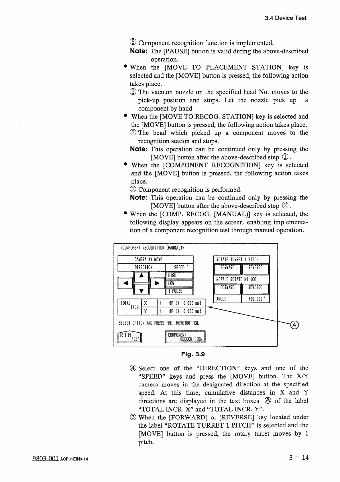
•
When
the
[
COMP
.
RECOG
.
(
MANUAL
)
]
key
is
selected
,
the
following
display
appears
on
the
screen
,
enabling
implementa
-
tion
of
a
component
recognition
test
through
manual
operation
.
to
the
moves
be
continued
only
by
pressing
the
can
〈
COMPONENT
RECOGNITION
(
MANUAL
)
>
CAMERA
-
XY
MOVE
ROTATE
TURRET
1
PITCH
DIRECTION
SPEED
FORWARD
I
REVERSE
HIGH
NOZZLE
ROTATE
N
1
JOG
气
►
墜
FORWARD
I
REVERSf
LSE
子
99.999
‘
ANGLE
t
OP
(
f
o
.
ooomm
)
TOTAL
X
I
NCR
.
t
OP
u
o
.
ooo
m
)
SELECT
OPTION
AND
PRESS
1
HE
[
MOVE
]
BUTTON
.
h
,
二
J
Fig
.
3.9
④
Select
one
of
the
“
DIRECTION
”
keys
and
“
SPEED
”
keys
and
press
the
[
MOVE
]
button
.
The
X
/
Y
camera
moves
in
the
designated
direction
at
the
specified
speed
.
At
this
time
,
cumulative
distances
in
X
and
Y
directions
are
displayed
in
the
text
boxes
@
of
the
label
“
TOTAL
INCR
.
X
”
and
“
TOTAL
INCR
.
Y
”
.
⑤
When
the
[
FORWARD
]
or
[
REVERSE
]
key
located
under
the
label
“
ROTATE
TURRET
1
PITCH
”
is
selected
and
the
[
MOVE
]
button
is
pressed
,
the
rotary
turret
moves
by
1
pitch
.
of
the
one
Qsn
^
-
nm
ACP
01
EIN
3
-
14