3MAINTENANCE__O.pdf - 第58页
1.4 Maintenance ( 5 ) Confirmation Points ( Before Attachment of Round or Reflective Nozzle ) 參 Confirmation of Nozzle Attachment Angle Perform the teaching operation for head origin and head / nozzle offset data in this…
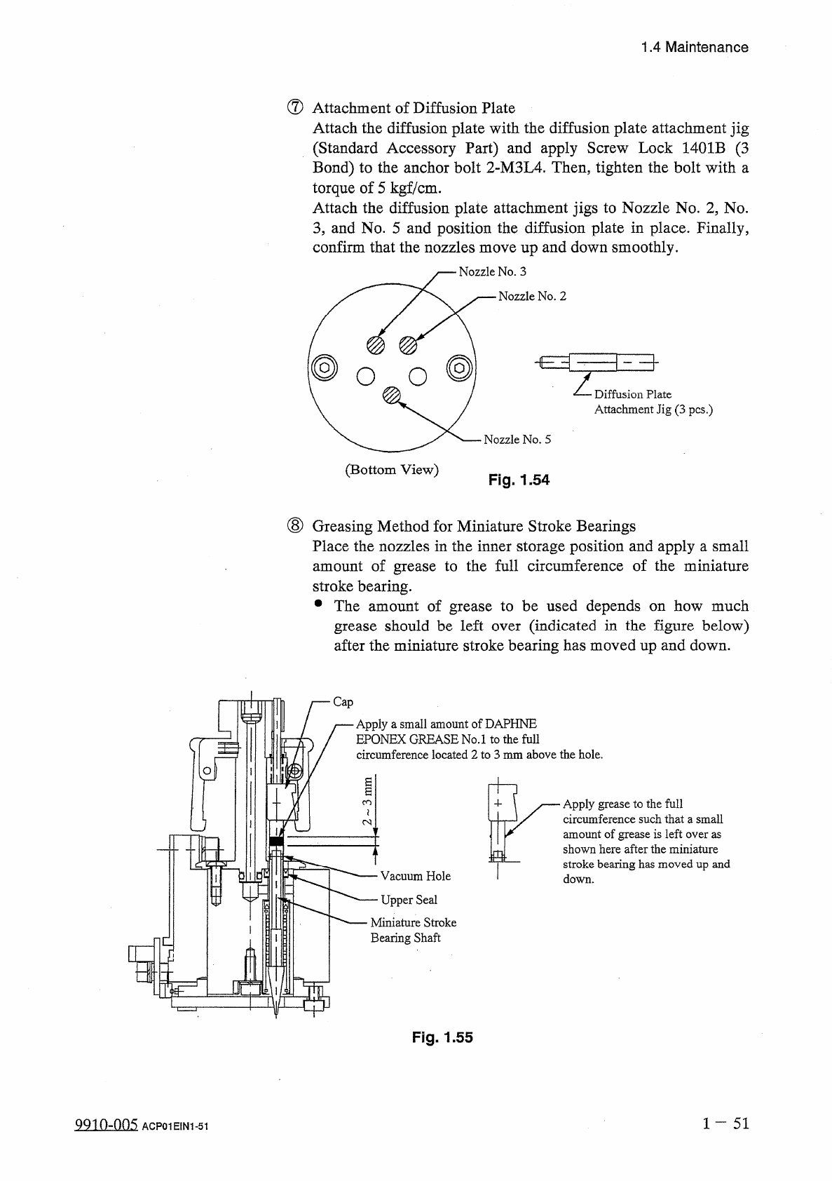
Vacuum
Hole
Upper
Seal
Apply
grease
to
the
full
circumference
such
that
a
small
amount
of
grease
is
left
over
as
shown
here
after
the
miniature
stroke
bearing
has
moved
up
and
down
.
H
—
Cap
Apply
a
small
amount
of
DAPHNE
EPONEX
GREASE
No
.
1
to
the
full
circumference
located
2
to
3
mm
above
the
hole
.
1.4
Maintenance
⑦
Attachment
of
Diffusion
Plate
Attach
the
diffusion
plate
with
the
diffusion
plate
attachment
jig
(
Standard
Accessory
Part
)
and
apply
Screw
Lock
1401
B
(
3
Bond
)
to
the
anchor
bolt
2
-
M
3
L
4
.
Then
,
tighten
the
bolt
with
a
torque
of
5
kgf
/
cm
.
Attach
the
diffusion
plate
attachment
jigs
to
Nozzle
No
.
2
,
No
.
3
,
and
No
.
5
and
position
the
diffusion
plate
in
place
.
Finally
,
confirm
that
the
nozzles
move
up
and
down
smoothly
.
j
—
Nozzle
No
.
3
Nozzle
No
.
2
@
O
O
Z
Diffusion
Plate
Attachment
Jig
(
3
pcs
.
)
Nozzle
No
.
5
(
Bottom
View
)
Fig
.
1.54
(
8
)
Greasing
Method
for
Miniature
Stroke
Bearings
Place
the
nozzles
in
the
inner
storage
position
and
apply
a
small
amount
of
grease
to
the
full
circumference
of
the
miniature
stroke
bearing
.
•
The
amount
of
grease
to
be
used
depends
on
how
much
grease
should
be
left
after
the
miniature
stroke
bearing
has
moved
up
and
down
.
(
indicated
in
the
figure
below
)
over
Miniature
Stroke
Bearing
Shaft
Q
Fig
.
1.55
1
~
51
Q
9
in
-
nn
5
ACP
01
EIN
1
-
51
UIUICO
iif
1.4
Maintenance
(
5
)
Confirmation
Points
(
Before
Attachment
of
Round
or
Reflective
Nozzle
)
參
Confirmation
of
Nozzle
Attachment
Angle
Perform
the
teaching
operation
for
head
origin
and
head
/
nozzle
offset
data
in
this
order
.
When
a
cylindrical
or
a
0603
component
is
used
,
perform
the
component
recognition
test
to
confirm
that
the
nozzle
is
attached
at
an
angle
of
5
degrees
or
less
(
X
and
Y
direction
on
the
recognition
monitor
)
.
If
the
angle
exceeds
5
degrees
,
follow
the
instructions
given
in
u
®
Cap
Attachment
”
and
go
through
the
subsequent
procedures
again
.
1
一
52
QQ
10
-
nn
5
1.4
Maintenance
1.4
.
5
Detachment
and
Attachment
of
Component
Drop
Prevention
Covers
(
Tray
)
The
power
breaker
should
be
turned
off
before
maintenance
work
.
Lock
the
power
breaker
in
“
OFF
”
mode
with
the
padlock
before
maintenance
work
.
A
CAUTION
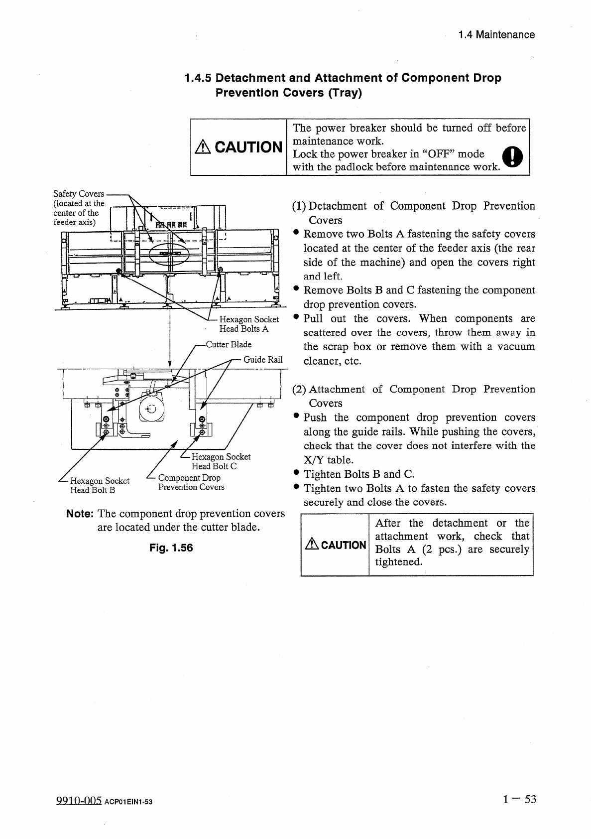
Safety
Covers
(
located
at
the
center
of
the
feeder
axis
)
V
.
(
1
)
Detachment
of
Component
Drop
Prevention
Covers
•
Remove
two
Bolts
A
fastening
the
safety
covers
located
at
the
center
of
the
feeder
axis
(
the
rear
side
of
the
machine
)
and
open
the
covers
right
and
left
.
目目目
•
Remove
Bolts
B
and
C
fastening
the
component
drop
prevention
covers
.
Hexagon
Socket
•
Pull
out
the
covers
.
When
components
Head
Bolts
A
are
scattered
over
the
covers
,
throw
them
away
in
the
scrap
box
or
cleaner
,
etc
.
•
Cutter
Blade
them
with
remove
a
vacuum
Guide
Rail
(
2
)
Attachment
of
Component
Drop
Prevention
Covers
•
Push
the
component
drop
prevention
along
the
guide
rails
.
While
pushing
the
covers
,
check
that
the
cover
does
not
interfere
with
the
X
/
Y
table
.
•
Tighten
Bolts
B
and
C
.
•
Tighten
two
Bolts
A
to
fasten
the
safety
covers
securely
and
close
the
covers
.
i
tti
1
covers
/
乙
Hexagon
Socket
,
Head
Bolt
C
Component
Drop
Prevention
Covers
Hexagon
Socket
Head
Bolt
B
Note
:
The
component
drop
prevention
covers
are
located
under
the
cutter
blade
.
After
the
detachment
or
the
attachment
work
,
check
that
Bolts
A
(
2
pcs
.
)
are
securely
tightened
.
A
CAUTION
Fig
.
1.56
1
-
53
QQ
10
-
005
ACP
01
EIN
1
-
53