3MAINTENANCE__O.pdf - 第67页
1.5 Checklist for Maintenance 1.5 Checklist for Maintenance Described in this session is how to perform the periodic maintenance . Use the tables as checklists . Refer to “ 1.3 Maintenance Spots ” for maintenance of each…
1.4
Maintenance
1.4
.
9
Replacement
of
Unrequired
Nozzle
Storage
and
Nozzle
Level
Selection
Plates
(
1
)
Time
of
Replacement
Replace
the
plate
whenever
a
dent
(
approx
.
0.2
mm
)
is
made
on
the
surface
.
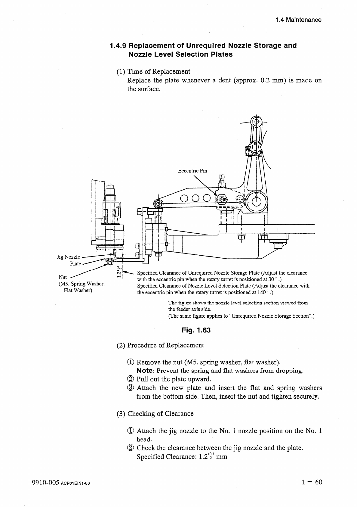
Eccentric
Pin
£
2
O O O
Jig
Nozzle
Plate
Specified
Clearance
of
Unrequired
Nozzle
Storage
Plate
(
Adjust
the
clearance
with
the
eccentric
pin
when
the
rotary
turret
is
positioned
at
30
。
•
)
Specified
Clearance
of
Nozzle
Level
Selection
Plate
(
Adjust
the
clearance
with
2
Nut
(
M
5
,
Spring
Washer
,
Flat
Washer
)
the
eccentric
pin
when
the
rotary
turret
is
positioned
at
140
°
.
)
The
figure
shows
the
nozzle
level
selection
section
viewed
from
the
feeder
axis
side
.
(
The
same
figure
applies
to
“
Unrequired
Nozzle
Storage
Section
’
’
.
)
Fig
.
1.63
(
2
)
Procedure
of
Replacement
①
Remove
the
nut
(
M
5
,
spring
washer
,
flat
washer
)
.
Note
:
Prevent
the
spring
and
flat
washers
from
dropping
.
②
Pull
out
the
plate
upward
.
③
Attach
the
from
the
bottom
side
.
Then
,
insert
the
nut
and
tighten
securely
.
plate
and
insert
the
flat
and
spring
washers
new
(
3
)
Checking
of
Clearance
①
Attach
the
jig
nozzle
to
the
No
.
1
nozzle
position
on
the
No
.
1
head
.
②
Check
the
clearance
between
the
jig
nozzle
and
the
plate
.
Specified
Clearance
:
1.2
T
mm
1
60
9910
-
005
ACP
01
EIN
1
-
60
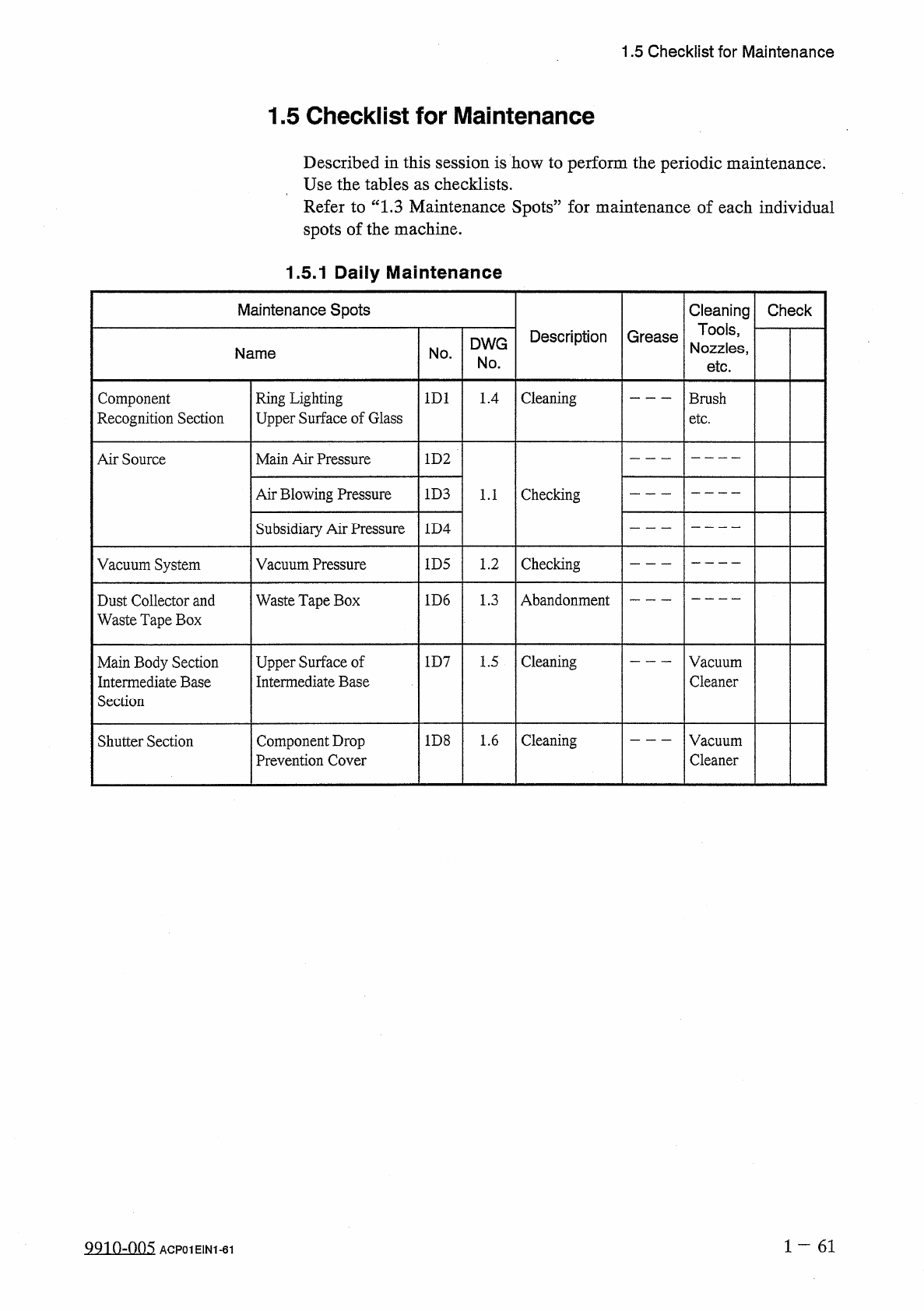
1.5
Checklist
for
Maintenance
1.5
Checklist
for
Maintenance
Described
in
this
session
is
how
to
perform
the
periodic
maintenance
.
Use
the
tables
as
checklists
.
Refer
to
“
1.3
Maintenance
Spots
”
for
maintenance
of
each
individual
spots
of
the
machine
.
1.5
.
1
Daily
Maintenance
Maintenance
Spots
Cleaning
Tools
,
Nozzles
,
Check
Description
Grease
DWG
Name
No
.
No
.
etc
.
Cleaning
Component
Recognition
Section
Ring
Lighting
Upper
Surface
of
Glass
1
D
1
1.4
Brush
etc
.
Main
Air
Pressure
Air
Source
1
D
2
Air
Blowing
Pressure
1
D
3
Checking
1.1
Subsidiary
Air
Pressure
1
D
4
Checking
Vacuum
System
Vacuum
Pressure
1
D
5
1.2
Abandonment
1
D
6
1.3
Dust
Collector
and
Waste
Tape
Box
Waste
Tape
Box
Upper
Surface
of
Intermediate
Base
Cleaning
Main
Body
Section
Intermediate
Base
Section
1
D
7
1.5
Vacuum
Cleaner
Cleaning
1
D
8
1.6
Vacuum
Cleaner
Shutter
Section
Component
Drop
Prevention
Cover
1
一
61
QQ
10
-
005
ACP
01
E
1
N
1
-
61
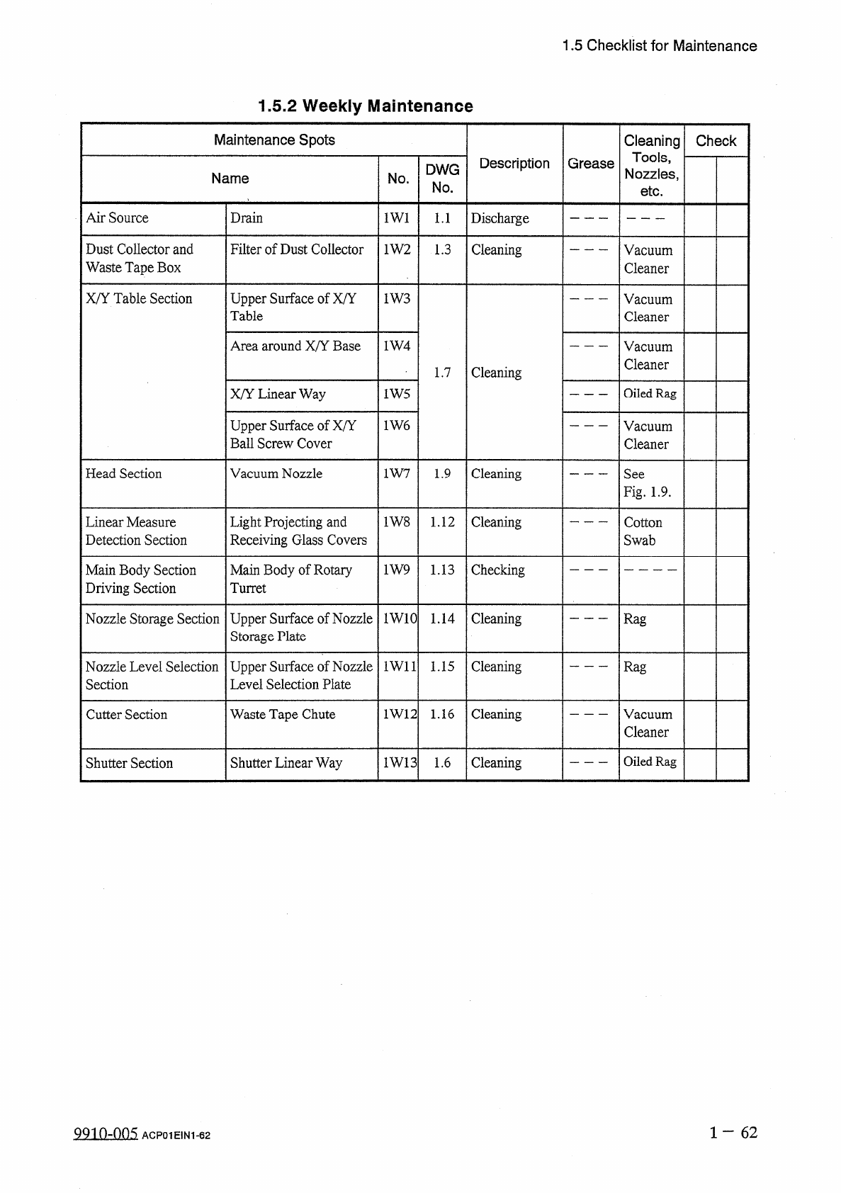
1.5
Checklist
for
Maintenance
1.5
.
2
Weekly
Maintenance
Maintenance
Spots
Cleaning
Tools
,
Nozzles
,
Check
Description
Grease
DWG
Name
No
.
No
.
etc
.
Air
Source
Drain
1
W
1
Discharge
1.1
Filter
of
Dust
Collector
Dust
Collector
and
Waste
Tape
Box
1
W
2
Cleaning
1.3
Vacuum
Cleaner
X
/
Y
Table
Section
Upper
Surface
of
X
/
Y
Table
1
W
3
Vacuum
Cleaner
Area
around
X
/
Y
Base
1
W
4
Vacuum
Cleaner
Cleaning
1.7
X
/
Y
Linear
Way
Oiled
Rag
1
W
5
Upper
Surface
of
X
/
Y
Ball
Screw
Cover
1
W
6
Vacuum
Cleaner
Head
Section
Vacuum
Nozzle
Cleaning
1
W
7
1.9
See
Fig
.
1.9
.
Light
Projecting
and
Receiving
Glass
Covers
Cleaning
Linear
Measure
Detection
Section
1
W
8
1.12
Cotton
Swab
Main
Body
of
Rotaiy
Turret
Checking
Main
Body
Section
Driving
Section
1
W
9
1.13
Upper
Surface
of
Nozzle
Storage
Plate
Cleaning
Nozzle
Storage
Section
1
W
10
1.14
Rag
Nozzle
Level
Selection
Section
Upper
Surface
of
Nozzle
Level
Selection
Plate
1
W
11
Cleaning
1.15
Rag
Cleaning
Waste
Tape
Chute
1
W
12
1.16
Cutter
Section
Vacuum
Cleaner
Oiled
Rag
Shutter
Linear
Way
1
W
13
1.6
Cleaning
Shutter
Section
1
—
6 2
99
in
-
nn
5
ACP
01
EIN
1
-
62