3MAINTENANCE__O.pdf - 第109页
3.4 Device Test ■ Setting of Hysteresis Test • When the [ HYSTERESIS TEST ] key is pressed at the “ COMPONENT RECOG . TEST ” display , the following display appears on the screen . 《 HYSTERESIS TEST ) RESULT OF HYSTERESI…
i
2
SEARCH
uuuuJuuujJilJiluJJ
KKKKKKKKKKKKKKKK
LLLLILLLLLLLLLLL
關
M
_
_
M
酬
MM
腳丽
_
醒酬
OOOOOOOOOOOOOOOQ
COMPONENT
11
12
13
14
15
llli
5555555555555555
▲
6666666666666666
iiiiimiimiii
3333333333333333
▼
4444444444444444
5555555555555555
6666666666666666
3.4
Device
Test
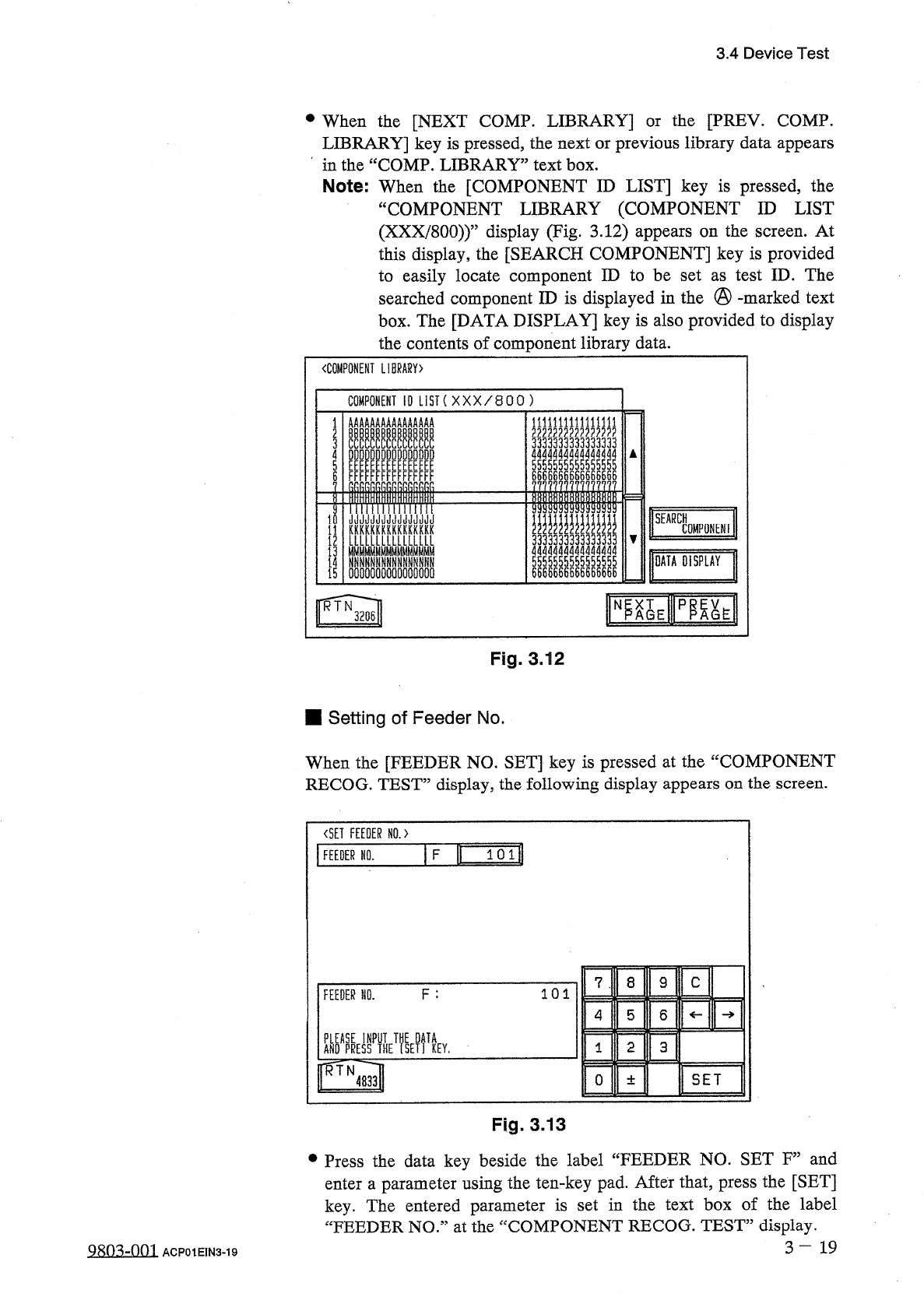
•
When
the
[
NEXT
COMP
.
LIBRARY
]
LIBRARY
]
key
is
pressed
,
the
next
or
previous
library
data
appears
in
the
“
COMP
.
LIBRARY
”
text
box
.
Note
:
When
the
[
COMPONENT
ID
LIST
]
key
is
pressed
,
the
“
COMPONENT
LIBRARY
(
COMPONENT
ID
LIST
(
XXX
/
800
)
)
”
display
(
Fig
.
3.12
)
appears
on
the
screen
.
At
this
display
,
the
[
SEARCH
COMPONENT
]
key
is
provided
to
easily
locate
component
ID
to
be
set
as
test
ID
.
The
searched
component
ID
is
displayed
in
the
@
-
marked
text
box
.
The
[
DATA
DISPLAY
]
key
is
also
provided
to
display
the
contents
of
component
library
data
.
the
[
PREY
.
COMP
.
or
〈
COMPONENT
LIBRARY
)
COMPONENT
10
LIST
(
XXX
/
800
)
臨
E
PP
^
E
N
RTN
3206
Fig
.
3.12
■
Setting
of
Feeder
No
.
When
the
[
FEEDER
NO
.
SET
]
key
is
pressed
at
the
“
COMPONENT
RECOG
.
TEST
”
display
,
the
following
display
appears
on
the
screen
.
〈
SET
FEEDER
N
0
.
>
F
B
101
FEEDER
NO
.
8
9
C
7
F
:
101
FEEDER
NO
.
4
5
6
關喘
EmkT
?
yp
2
3
1
KEY
.
rrfN
SET
0
4833
±
Fig
.
3
,
13
•
Press
the
data
key
beside
the
label
“
FEEDER
NO
.
SET
F
”
and
enter
a
parameter
using
the
ten
-
key
pad
.
After
that
,
press
the
[
SET
]
key
.
The
entered
parameter
is
set
in
the
text
box
of
the
label
“
FEEDER
NO
”
at
the
“
COMPONENT
RECOG
.
TEST
”
display
.
3
-
19
ACP
01
EIN
3
-
19
DATA
DISPLAY
AAB
8
CCDDEEFFRR
II
AKRUrunurr
-
c
ABCDEFnn
ABCDCLFPn
ABn
-
r
-
rrpn
ABC
nucLFnh
»
HnDnlunuF
-
rrrth
ADUCnwpuF
ABCDEF
AOCDEFnh
ABC
nwsLLFAh
1
i
2
T
04
PD
67
^
3.4
Device
Test
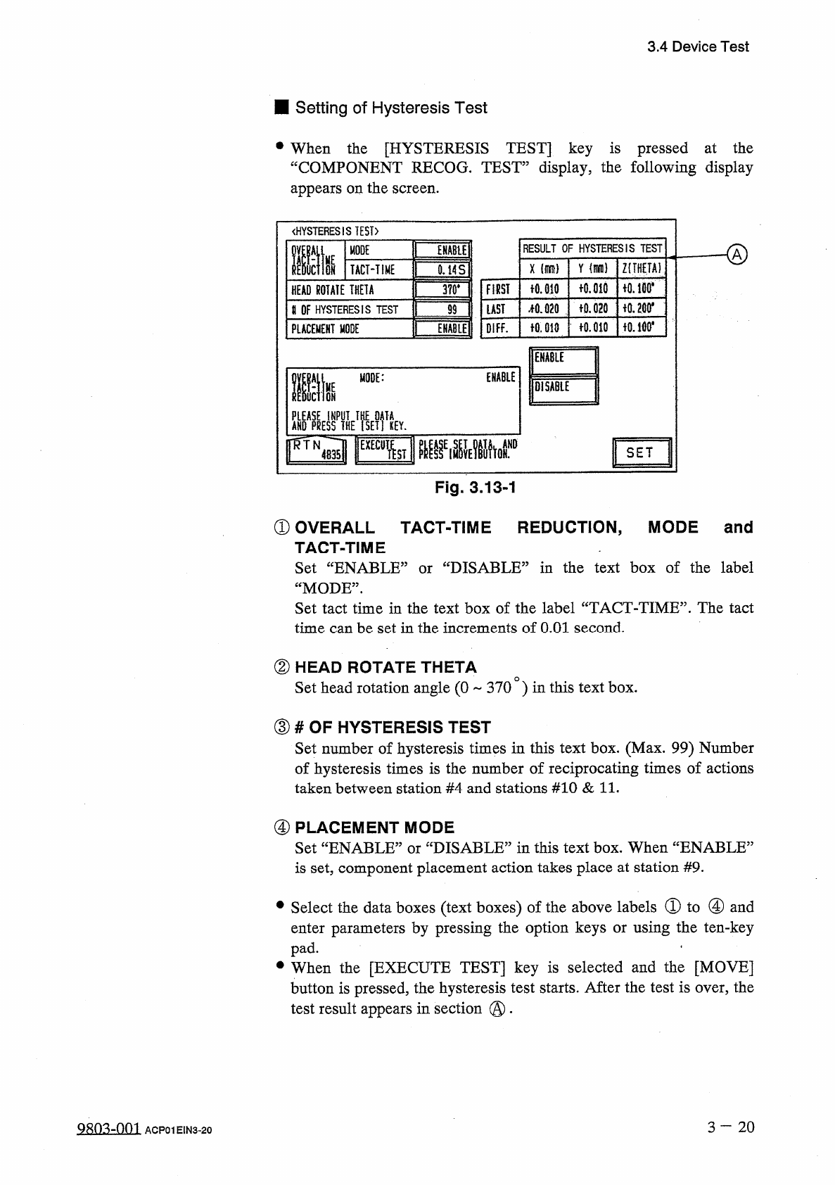
■
Setting
of
Hysteresis
Test
•
When
the
[
HYSTERESIS
TEST
]
key
is
pressed
at
the
“
COMPONENT
RECOG
.
TEST
”
display
,
the
following
display
appears
on
the
screen
.
《
HYSTERESIS
TEST
)
RESULT
OF
HYSTERESIS
TEST
MODE
ffit
ENABU
HE
Y
Z
(
THETA
)
X
ON
TACT
-
TIME
0.14
S
fO
.
md
iO
.
lBO
*
FIRST
十
0.010
HEAD
ROTATE
THETA
3
?
0
.
令
0.200
*
f
0.020
疏
020
LAST
U
OF
HYSTERESIS
TEST
99
fO
.
010
f
0.010
OIFF
.
PLACEMENT
MODE
ENABLE
Mm
ENABLE
life
MODE
:
lOiSABlE
AKO
^
yflHE
^
ETfiEY
.
SET
Fig
.
3.13
-
1
①
OVERALL
TACT
-
TIME
REDUCTION
,
MODE
and
TACT
-
TIME
Set
“
ENABLE
1
“
MODE
”
.
Set
tact
time
in
the
text
box
of
the
label
“
TACT
-
TIME
”
.
The
tact
time
can
be
set
in
the
increments
of
O
.
Ol
second
.
'
DISABLE
^
in
the
text
box
of
the
label
or
②
HEAD
ROTATE
THETA
Set
head
rotation
angle
(
0
370
)
in
this
text
box
.
③
#
OF
HYSTERESIS
TEST
Set
number
of
hysteresis
times
in
this
text
box
.
(
Max
.
99
)
Number
of
hysteresis
times
is
the
number
of
reciprocating
times
of
actions
taken
between
station
#
4
and
stations
#
10
&
11
.
④
PLACEMENT
MODE
Set
“
ENABLE
”
or
“
DISABLE
”
in
this
text
box
.
When
“
ENABLE
5
is
set
,
component
placement
action
takes
place
at
station
#
9
.
•
Select
the
data
boxes
(
text
boxes
)
of
the
above
labels
①
to
④
and
enter
parameters
by
pressing
the
option
keys
or
using
the
ten
-
key
pad
.
.
•
When
the
[
EXECUTE
TEST
]
key
is
selected
and
the
[
MOVE
]
button
is
pressed
,
the
hysteresis
test
starts
.
After
the
test
is
over
,
the
test
result
appears
in
section
@
.
3
-
20
糊
3
-
001
ACP
01
EIN
3
-
20
3.5
Offset
Teaching
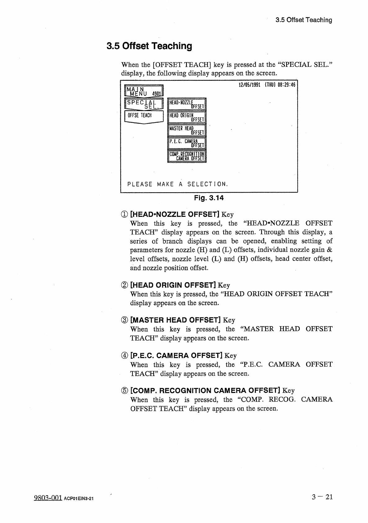
3.5
Offset
Teaching
When
the
[
OFFSET
TEACH
]
key
is
pressed
at
the
“
SPECIAL
SEL
.
:
display
,
the
following
display
appears
on
the
screen
.
12
/
05
/
1991
(
THU
)
08
:
29
:
46
m
N
NU
4901
HEAD
-
NOZZLE
FFSEI
OFFSE
TEACH
HEAD
ORIGIN
OFFSET
MASTER
WHisEH
P
.
E
.
C
.
gaga
PLEASE
MAKE
A
SELECTION
.
Fig
.
3.14
①
[
HEAD
.
NOZZLE
OFFSET
]
Key
When
this
key
is
pressed
,
the
“
HEAI
>
NOZZLE
OFFSET
TEACH
”
display
appears
on
the
screen
.
Through
this
display
,
a
series
of
branch
displays
parameters
for
nozzle
(
H
)
and
(
L
)
offsets
,
individual
nozzle
gain
&
level
offsets
,
nozzle
level
(
L
)
and
(
H
)
offsets
,
head
center
offset
,
and
nozzle
position
offset
.
be
opened
,
enabling
setting
of
can
②
[
HEAD
ORIGIN
OFFSET
]
Key
When
this
key
is
pressed
,
the
“
HEAD
ORIGIN
OFFSET
TEACH
5
display
appears
on
the
screen
.
③
[
MASTER
HEAD
OFFSET
]
Key
When
this
key
is
pressed
,
TEACH
”
display
appears
on
the
screen
.
the
“
MASTER
HEAD
OFFSET
④
[
P
.
E
.
C
.
CAMERA
OFFSET
]
Key
When
this
key
is
pressed
,
TEACH
”
display
appears
on
the
screen
.
the
"
P
.
E
.
C
.
CAMERA
OFFSET
⑤
[
COMP
.
RECOGNITION
CAMERA
OFFSET
]
Key
When
this
key
is
pressed
,
the
“
COMP
.
RECOG
.
CAMERA
OFFSET
TEACH
”
display
appears
on
the
screen
.
3
—
21
Q
8
ft
3
-
nm
ACP
01
EIN
3
-
21