3MAINTENANCE__O.pdf - 第110页
3.5 Offset Teaching 3.5 Offset Teaching When the [ OFFSET TEACH ] key is pressed at the “ SPECIAL SEL . : display , the following display appears on the screen . 12 / 05 / 1991 ( THU ) 08 : 29 : 46 m N NU 4901 HEAD - NOZ…
3.4
Device
Test
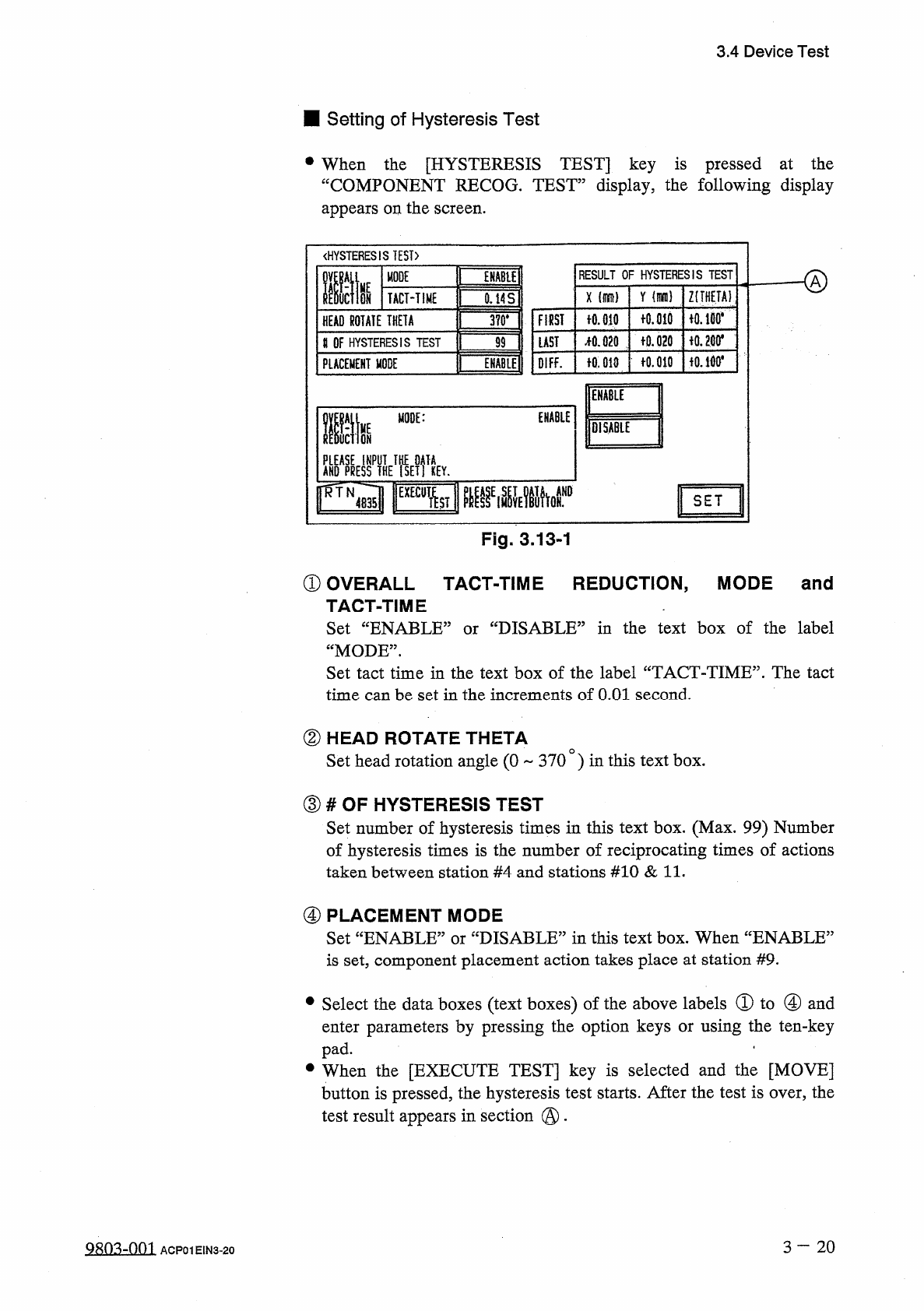
■
Setting
of
Hysteresis
Test
•
When
the
[
HYSTERESIS
TEST
]
key
is
pressed
at
the
“
COMPONENT
RECOG
.
TEST
”
display
,
the
following
display
appears
on
the
screen
.
《
HYSTERESIS
TEST
)
RESULT
OF
HYSTERESIS
TEST
MODE
ffit
ENABU
HE
Y
Z
(
THETA
)
X
ON
TACT
-
TIME
0.14
S
fO
.
md
iO
.
lBO
*
FIRST
十
0.010
HEAD
ROTATE
THETA
3
?
0
.
令
0.200
*
f
0.020
疏
020
LAST
U
OF
HYSTERESIS
TEST
99
fO
.
010
f
0.010
OIFF
.
PLACEMENT
MODE
ENABLE
Mm
ENABLE
life
MODE
:
lOiSABlE
AKO
^
yflHE
^
ETfiEY
.
SET
Fig
.
3.13
-
1
①
OVERALL
TACT
-
TIME
REDUCTION
,
MODE
and
TACT
-
TIME
Set
“
ENABLE
1
“
MODE
”
.
Set
tact
time
in
the
text
box
of
the
label
“
TACT
-
TIME
”
.
The
tact
time
can
be
set
in
the
increments
of
O
.
Ol
second
.
'
DISABLE
^
in
the
text
box
of
the
label
or
②
HEAD
ROTATE
THETA
Set
head
rotation
angle
(
0
370
)
in
this
text
box
.
③
#
OF
HYSTERESIS
TEST
Set
number
of
hysteresis
times
in
this
text
box
.
(
Max
.
99
)
Number
of
hysteresis
times
is
the
number
of
reciprocating
times
of
actions
taken
between
station
#
4
and
stations
#
10
&
11
.
④
PLACEMENT
MODE
Set
“
ENABLE
”
or
“
DISABLE
”
in
this
text
box
.
When
“
ENABLE
5
is
set
,
component
placement
action
takes
place
at
station
#
9
.
•
Select
the
data
boxes
(
text
boxes
)
of
the
above
labels
①
to
④
and
enter
parameters
by
pressing
the
option
keys
or
using
the
ten
-
key
pad
.
.
•
When
the
[
EXECUTE
TEST
]
key
is
selected
and
the
[
MOVE
]
button
is
pressed
,
the
hysteresis
test
starts
.
After
the
test
is
over
,
the
test
result
appears
in
section
@
.
3
-
20
糊
3
-
001
ACP
01
EIN
3
-
20
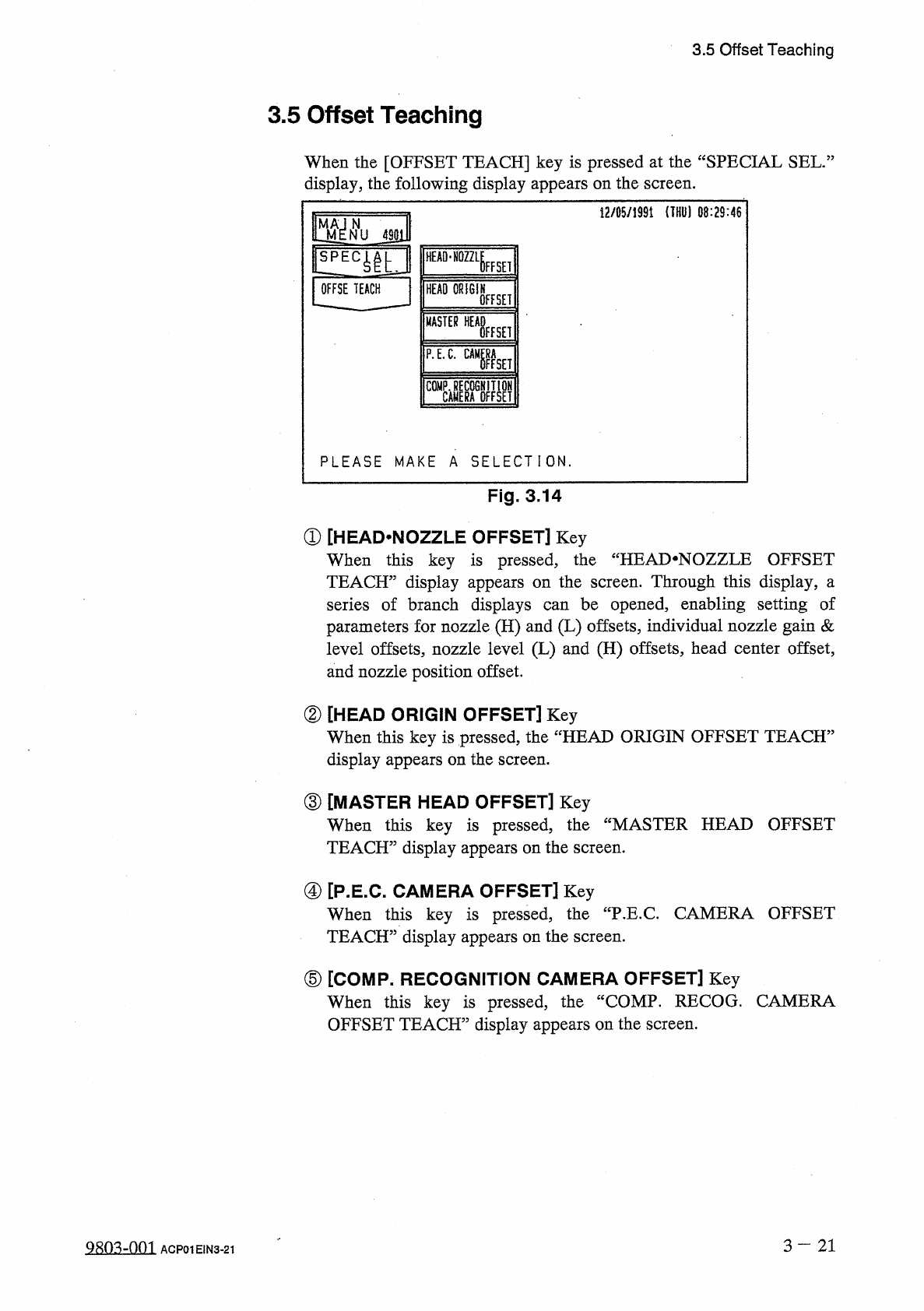
3.5
Offset
Teaching
3.5
Offset
Teaching
When
the
[
OFFSET
TEACH
]
key
is
pressed
at
the
“
SPECIAL
SEL
.
:
display
,
the
following
display
appears
on
the
screen
.
12
/
05
/
1991
(
THU
)
08
:
29
:
46
m
N
NU
4901
HEAD
-
NOZZLE
FFSEI
OFFSE
TEACH
HEAD
ORIGIN
OFFSET
MASTER
WHisEH
P
.
E
.
C
.
gaga
PLEASE
MAKE
A
SELECTION
.
Fig
.
3.14
①
[
HEAD
.
NOZZLE
OFFSET
]
Key
When
this
key
is
pressed
,
the
“
HEAI
>
NOZZLE
OFFSET
TEACH
”
display
appears
on
the
screen
.
Through
this
display
,
a
series
of
branch
displays
parameters
for
nozzle
(
H
)
and
(
L
)
offsets
,
individual
nozzle
gain
&
level
offsets
,
nozzle
level
(
L
)
and
(
H
)
offsets
,
head
center
offset
,
and
nozzle
position
offset
.
be
opened
,
enabling
setting
of
can
②
[
HEAD
ORIGIN
OFFSET
]
Key
When
this
key
is
pressed
,
the
“
HEAD
ORIGIN
OFFSET
TEACH
5
display
appears
on
the
screen
.
③
[
MASTER
HEAD
OFFSET
]
Key
When
this
key
is
pressed
,
TEACH
”
display
appears
on
the
screen
.
the
“
MASTER
HEAD
OFFSET
④
[
P
.
E
.
C
.
CAMERA
OFFSET
]
Key
When
this
key
is
pressed
,
TEACH
”
display
appears
on
the
screen
.
the
"
P
.
E
.
C
.
CAMERA
OFFSET
⑤
[
COMP
.
RECOGNITION
CAMERA
OFFSET
]
Key
When
this
key
is
pressed
,
the
“
COMP
.
RECOG
.
CAMERA
OFFSET
TEACH
”
display
appears
on
the
screen
.
3
—
21
Q
8
ft
3
-
nm
ACP
01
EIN
3
-
21
3.5
Offset
Teaching
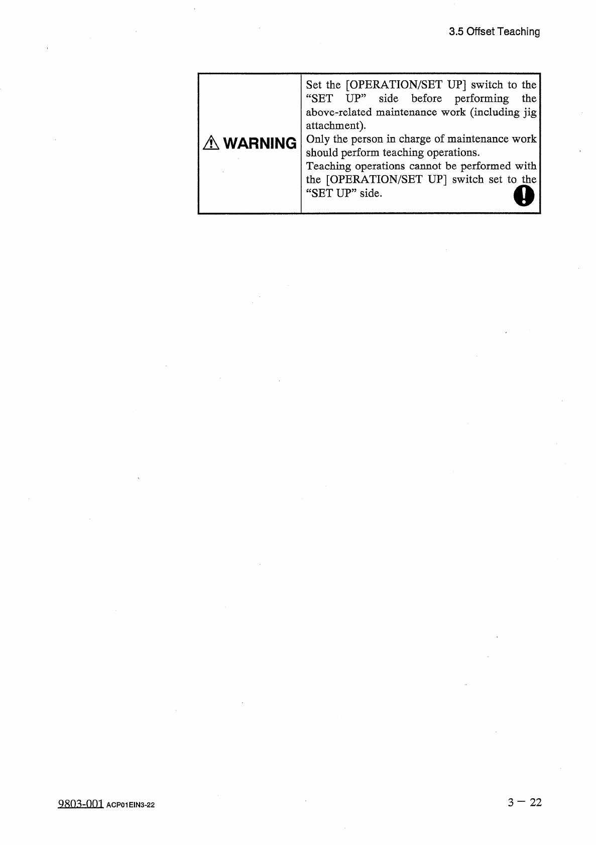
Set
the
[
OPERATION
/
SET
UP
]
switch
to
the
“
SET
UP
”
side
before
performing
the
above
-
related
maintenance
work
(
including
jig
attachment
)
.
Only
the
person
in
charge
of
maintenance
work
should
perform
teaching
operations
.
Teaching
operations
cannot
be
performed
with
the
[
OPERATION
/
SET
UP
]
switch
set
to
the
“
SET
UP
”
side
.
A
WARNING
3
-
2 2
9803
-
001
ACP
01
EIN
3
-
22