3MAINTENANCE__O.pdf - 第63页
1.4 Maintenance ( 3 ) Setting and Checking of P . C . B . Detection Photosensor ( See Fig . 2.9 ) Insert a thickness gauge between the chute reference plane and the end of the P . C . B . detection lever and check how a …
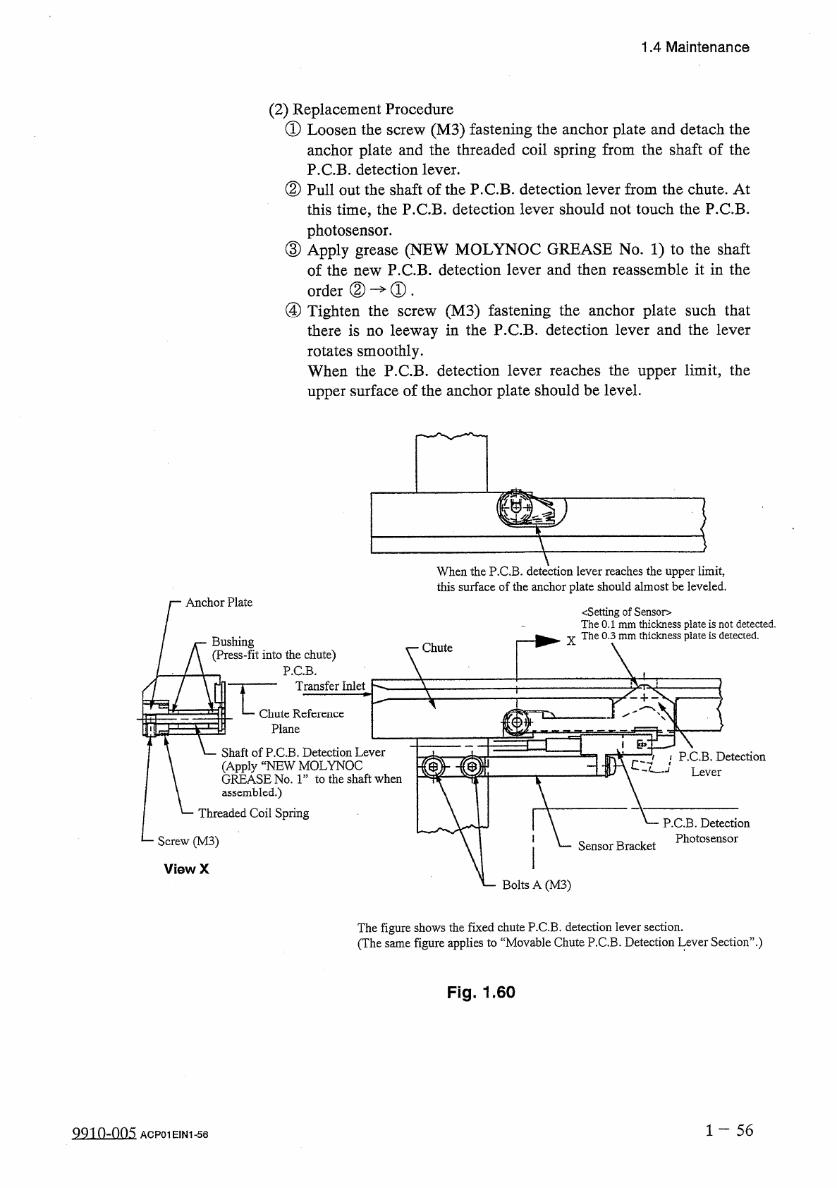
1.4
Maintenance
(
2
)
Replacement
Procedure
①
Loosen
the
screw
(
M
3
)
fastening
the
anchor
plate
and
detach
the
anchor
plate
and
the
threaded
coil
spring
from
the
shaft
of
the
P
.
C
.
B
.
detection
lever
.
②
Pull
out
the
shaft
of
the
P
.
C
.
B
.
detection
lever
from
the
chute
.
At
this
time
,
the
P
.
C
.
B
.
detection
lever
should
not
touch
the
P
.
C
.
B
.
photosensor
.
③
Apply
grease
(
NEW
MOLYNOC
GREASE
No
.
1
)
to
the
shaft
of
the
new
P
.
C
.
B
.
detection
lever
and
then
reassemble
it
in
the
order
②
—
①
.
④
Tighten
the
(
M
3
)
fastening
the
anchor
plate
such
that
there
is
no
leeway
in
the
P
.
C
.
B
.
detection
lever
and
the
lever
rotates
smoothly
.
When
the
P
.
C
.
B
.
detection
lever
reaches
the
upper
limit
,
the
upper
surface
of
the
anchor
plate
should
be
level
.
screw
When
the
P
.
C
.
B
.
detection
lever
reaches
the
upper
limit
,
this
surface
of
the
anchor
plate
should
almost
be
leveled
.
Anchor
Plate
〈
Setting
of
Sensor
>
The
0.1
mm
thickness
plate
is
not
detected
.
The
0.3
mm
thickness
plate
is
detected
.
X
Bushing
Chute
(
Press
-
fit
into
the
chute
)
P
.
C
.
B
.
Transfer
Inlet
7
^
-
Chute
Reference
Plane
通
Shaft
of
P
.
C
.
B
.
Detection
Lever
(
Apply
“
NEW
MOLYNOC
GREASE
No
.
1
”
to
the
shaft
when
assembled
.
)
Threaded
Coil
Spring
P
.
C
.
B
.
Detection
Lever
P
.
C
.
B
.
Detection
Photosensor
Screw
(
M
3
)
Sensor
Bracket
ViewX
L
Bolts
A
(
M
3
)
The
figure
shows
the
fixed
chute
P
.
C
.
B
.
detection
lever
section
.
(
The
same
figure
applies
to
“
Movable
Chute
P
.
C
.
B
.
Detection
Lever
Section
’
’
.
)
Fig
.
1.60
1
-
56
QQ
10
-
005
ACP
01
EIN
1
-
56
1.4
Maintenance
(
3
)
Setting
and
Checking
of
P
.
C
.
B
.
Detection
Photosensor
(
See
Fig
.
2.9
)
Insert
a
thickness
gauge
between
the
chute
reference
plane
and
the
end
of
the
P
.
C
.
B
.
detection
lever
and
check
how
a
P
.
C
.
B
.
is
detected
.
•
The
0.1
mm
thickness
plate
is
not
detected
.
•
The
0.3
mm
thickness
plate
is
detected
.
When
the
above
requirement
is
not
met
,
loosen
Bolts
A
(
M
3
)
and
move
the
sensor
bracket
up
Tighten
Bolts
A
(
M
3
)
at
a
place
where
the
sensor
bracket
is
correctly
positioned
and
set
securely
.
down
until
rightly
set
.
or
1
—
57
QQin
~
nn
5
ACP
01
E
1
N
1
-
57
1.4
Maintenance
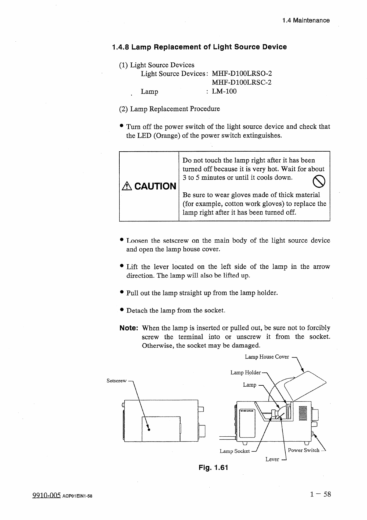
1.4
.
8
Lamp
Replacement
of
Light
Source
Device
(
1
)
Light
Source
Devices
Light
Source
Devices
:
MHF
-
DlOOLRSO
-
2
MHF
-
D
100
LRSC
-
2
:
LM
-
100
t
Lamp
(
2
)
Lamp
Replacement
Procedure
•
Turn
off
the
power
switch
of
the
light
source
device
and
check
that
the
LED
(
Orange
)
of
the
power
switch
extinguishes
.
Do
not
touch
the
lamp
right
after
it
has
been
turned
off
because
it
is
very
hot
.
Wait
for
about
3
to
5
minutes
or
until
it
cools
down
.
A
CAUTION
Be
sure
to
wear
gloves
made
of
thick
material
(
for
example
,
cotton
work
gloves
)
to
replace
the
lamp
right
after
it
has
been
turned
off
.
•
Loosen
the
setscrew
on
the
main
body
of
the
light
source
device
and
open
the
lamp
house
cover
.
•
Lift
the
lever
located
on
the
left
side
of
the
lamp
in
the
arrow
direction
.
The
lamp
will
also
be
lifted
up
.
•
Pull
out
the
lamp
straight
up
from
the
lamp
holder
.
•
Detach
the
lamp
from
the
socket
.
Note
:
When
the
lamp
is
inserted
or
pulled
out
,
be
sure
not
to
forcibly
screw
the
terminal
into
or
unscrew
it
from
the
socket
.
Otherwise
,
the
socket
may
be
damaged
.
Lamp
House
Cover
Lamp
Holder
.
Lamp
□
P
=
4
Lamp
Socket
Fig
.
1.61
1
-
58
991
0
-
005
ACP
01
EIN
1
-
58