3MAINTENANCE__O.pdf - 第133页
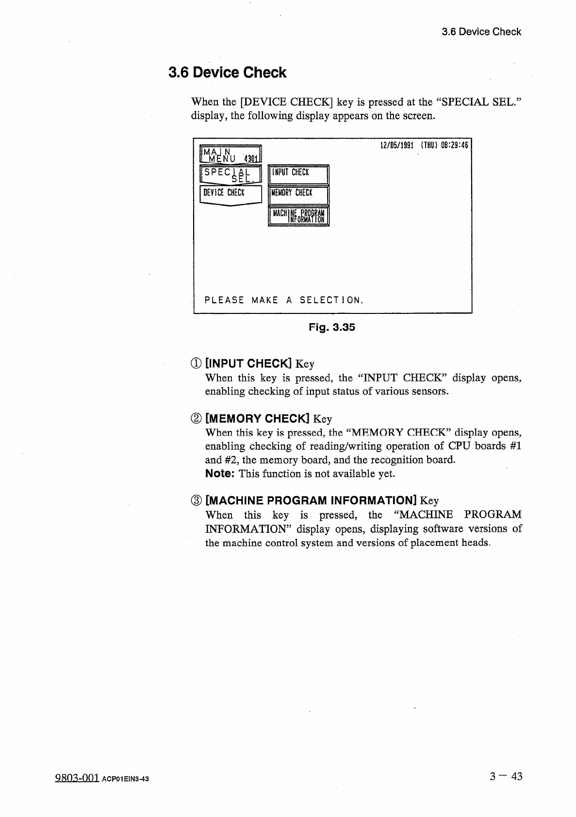
3.6 Device Check 3.6 Device Check When the [ DEVICE CHECK ] key is pressed at the “ SPECIAL SEL . : display , the following display appears on the screen . 12 / 05 / 1991 ( THU ) 0 B : 29 : 46 teffu 4 ml l ! LEC ^ U INPU…
3.5
Offset
Teaching
(
4
)
Attach
the
jig
nozzle
.
(
5
)
Select
the
[
SQUARE
JIG
(
MOVE
X
/
Y
TABLE
)
]
key
and
press
the
[
MOVE
]
button
.
•
The
X
/
Y
table
moves
to
an
area
under
the
jig
nozzle
.
(
6
)
Set
the
balancer
to
balance
the
jig
nozzle
.
(
X
=
十
20.00
mm
and
Y
=
+
46.50
mm
)
(
7
)
Select
the
[
MOVE
HEAD
TO
RECOGNITION
POSITION
]
key
and
press
the
[
MOVE
]
button
.
•
The
head
equipped
with
the
jig
nozzle
moves
to
the
recognition
station
.
•
The
X
/
Y
table
moves
to
its
origin
.
(
8
)
Enter
the
dimensions
of
the
jig
nozzle
.
•
Press
the
[
EDIT
DATA
]
key
.
The
“
COMP
.
RECOG
.
CAMERA
OFFSET
TEACH
_
EDIT
DATA
display
appears
on
the
screen
.
Enter
parameters
in
the
data
boxes
of
the
labels
“
CALIBRATION
JIG
SIZE
X
”
and
“
CALIBRATION
JIG
SIZE
Y
”
.
(
9
)
Perform
teaching
operation
.
•
Select
the
[
TEACH
CAMERA
#
1
&
#
2
,
CAMERA
OFFSET
]
key
and
press
the
[
MOVE
]
button
.
The
jig
nozzle
is
recognized
to
automatically
calculate
offset
values
for
“
CAMR
.
#
1
MAG
.
0.01
从
m
/
pixel
”
,
“
CAMR
.
#
2
MAG
.
0.01
Um
/
pixeY
\
“
ROTATION
”
,
and
“
CAMERA
#
1
_
CAMERA
#
2
OFFSET
”
.
•
Select
the
[
TEACH
CAMERA
ROTATION
OFFSET
]
key
and
press
the
[
MOVE
]
button
.
The
motion
calibration
function
is
implemented
to
automatically
calculate
sco
•
The
parameters
(
saved
values
)
displayed
in
updated
to
automatically
calculated
values
.
ion
offset
.
pe
rotat
@
are
automatically
(
10
)
Select
the
[
REMOVE
JIG
(
MOVE
X
/
Y
TABLE
)
]
key
and
press
the
[
MOVE
]
button
.
•
The
head
equipped
with
the
jig
nozzle
moves
to
a
position
where
the
nozzle
can
be
detached
.
•
The
X
/
Y
table
moves
slowly
to
a
position
where
the
jig
nozzle
can
be
detached
.
•
Detach
the
jig
nozzle
.
(
11
)
Press
the
[
VACUUM
VALVE
ON
/
OFF
]
key
to
turn
off
the
vacuum
valve
for
the
No
.
1
head
.
(
12
)
Detach
the
jig
nozzle
and
perform
nozzle
change
operation
.
(
13
)
Select
the
[
MOVE
X
/
Y
TABLE
TO
ORIGIN
POSITION
]
key
and
press
the
[
MOVE
]
button
.
•
The
X
/
Y
table
returns
to
its
origin
.
3
一
42
9803
-
001
ACP
01
EIN
3
-
42
3.6
Device
Check
3.6
Device
Check
When
the
[
DEVICE
CHECK
]
key
is
pressed
at
the
“
SPECIAL
SEL
.
:
display
,
the
following
display
appears
on
the
screen
.
12
/
05
/
1991
(
THU
)
0
B
:
29
:
46
teffu
4
ml
l
!
LEC
^
U
INPUT
CHECK
jDEVICE
CHECK
|
|
MEMORY
CHECK
nmi
PLEASE
MAKE
A
SELECTION
.
Fig
.
3.35
①
[
INPUT
CHECK
]
Key
When
this
key
is
pressed
,
the
“
INPUT
CHECK
”
display
opens
,
enabling
checking
of
input
status
of
various
sensors
.
②
[
MEMORY
CHECK
]
Key
When
this
key
is
pressed
,
the
“
MEMORY
CHECK
”
display
opens
,
enabling
checking
of
reading
/
writing
operation
of
CPU
boards
#
1
and
#
2
,
the
memory
board
,
and
the
recognition
board
.
Note
:
This
function
is
not
available
yet
.
③
[
MACHINE
PROGRAM
INFORMATION
]
Key
When
this
key
is
pressed
,
INFORMATION
”
display
opens
,
displaying
software
versions
of
the
machine
control
system
and
versions
of
placement
heads
.
the
“
MACHINE
PROGRAM
3
一
43
Q
朗
4
¥
)
1
ACP
01
EIN
3
-
43
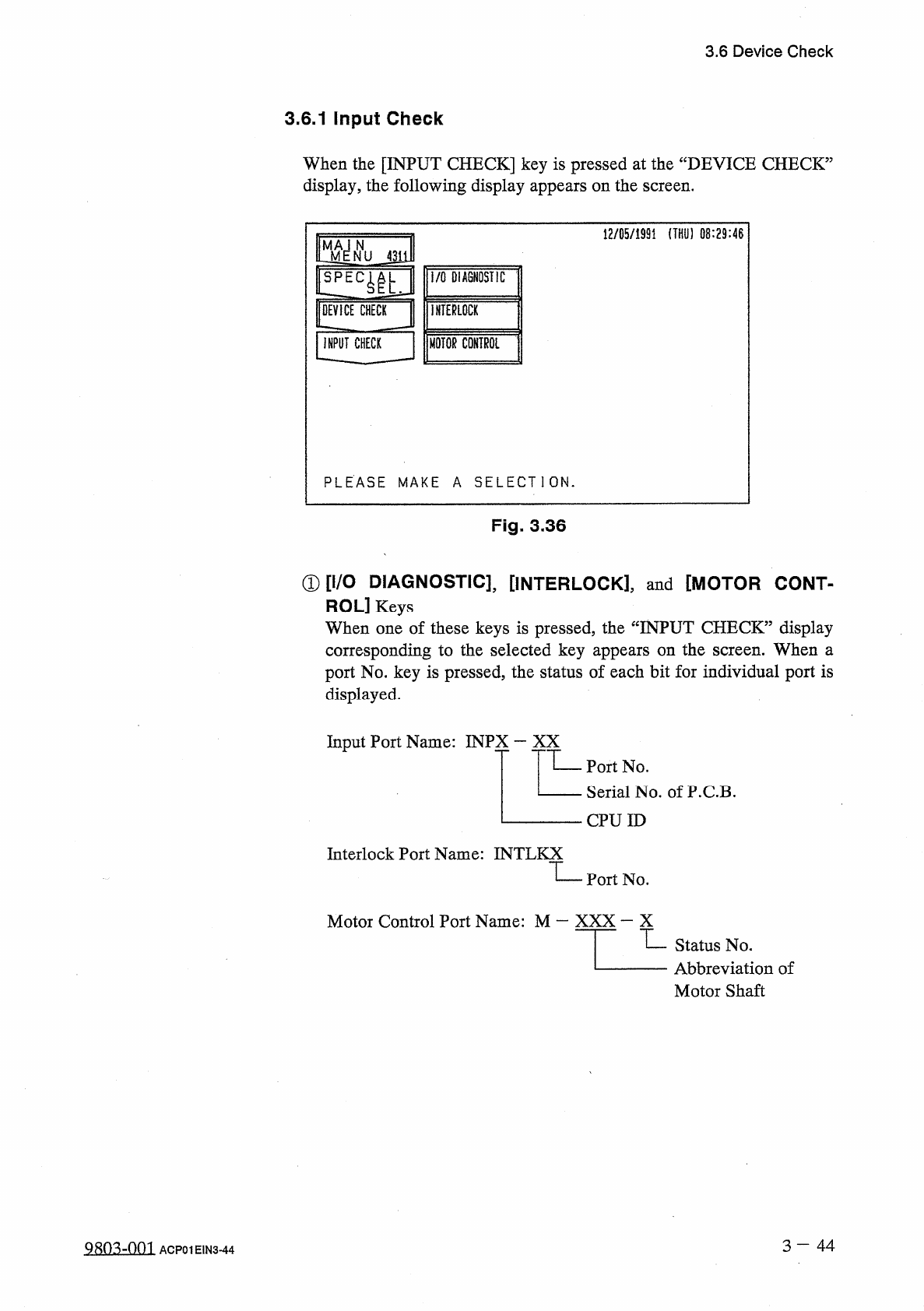
3.6
Device
Check
3.6
.
1
Input
Check
When
the
[
INPUT
CHECK
]
key
is
pressed
at
the
“
DEVICE
CHECK
5
display
,
the
following
display
appears
on
the
screen
.
12
/
85
/
1991
(
THU
)
08
:
29
:
46
J
311
urn
I
/
O
DIAGNOSTIC
INTERLOCK
DEVICE
CHECK
INPUT
CHECK
MOTOR
CONTROL
PLEASE
MAKE
A
SELECTION
.
Fig
.
3
-
36
①
[
I
/
O
DIAGNOSTIC
]
,
[
INTERLOCK
]
,
and
[
MOTOR
CONT
-
ROL
]
Keys
When
one
of
these
keys
is
pressed
,
the
“
INPUT
CHECK
”
display
corresponding
to
the
selected
key
appears
on
the
screen
.
When
a
port
No
.
key
is
pressed
,
the
status
of
each
bit
for
individual
port
is
displayed
.
Input
Port
Name
:
INPX
—
XX
Port
No
.
Serial
No
.
ofP
.
C
.
B
.
CPU
ID
Interlock
Port
Name
:
INTL
KX
Port
No
.
Motor
Control
Port
Name
:
M
—
XXX
—
X
Status
No
.
Abbreviation
of
Motor
Shaft
3
—
4 4
QRO
^
-
Om
ACP
01
EIN
3
-
44