3MAINTENANCE__O.pdf - 第130页
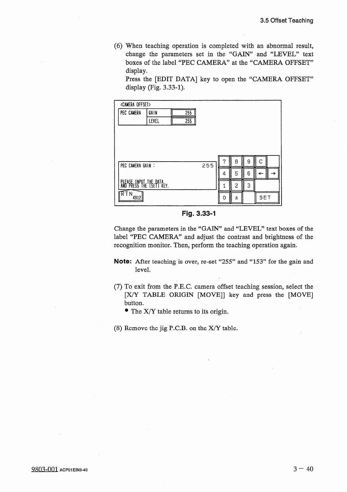
3.5 Offset Teaching ( 6 ) When teaching operation is completed with an abnormal result , change the parameters set in the “ GAIN ” and “ LEVEL ” text boxes of the label “ PEC CAMERA ” at the “ CAMERA OFFSET ” display . P…
3.5
Offset
Teaching
(
4
)
Move
the
X
/
Y
table
such
that
the
jig
P
.
C
.
B
.
calibration
mark
enters
the
visual
field
of
the
camera
as
follows
.
•
Select
the
[
FIDUCIAL
MARK
POSITION
[
MOVE
]
]
key
and
press
the
[
MOVE
]
button
.
The
X
/
Y
table
starts
moving
.
•
If
the
calibration
mark
cannot
be
positioned
correctly
in
the
visual
field
of
the
camera
,
open
the
“
X
/
Y
TABLE
MOVE
”
display
and
select
the
[
MANUAL
ALIGNMENT
[
MOVE
]
]
or
the
[
DESIGNATED
POSITION
[
MOVE
]
]
key
,
After
that
,
press
the
[
MOVE
]
button
to
move
the
X
/
Y
table
until
the
calibration
mark
is
correctly
positioned
.
Refer
to
“
[
Operation
of
X
/
Y
Table
Movement
]
”
in
“
3.4
.
2
P
.
E
.
C
.
Recognition
Test
”
for
details
.
(
5
)
Select
the
[
AUTO
TEACH
[
MOVE
]
]
key
and
press
the
[
MOVE
]
button
.
•
Offset
data
is
automatically
taught
through
motion
calibration
operation
.
•
The
parameters
(
saved
values
)
displayed
in
@
are
automatically
updated
to
automatically
calculated
values
.
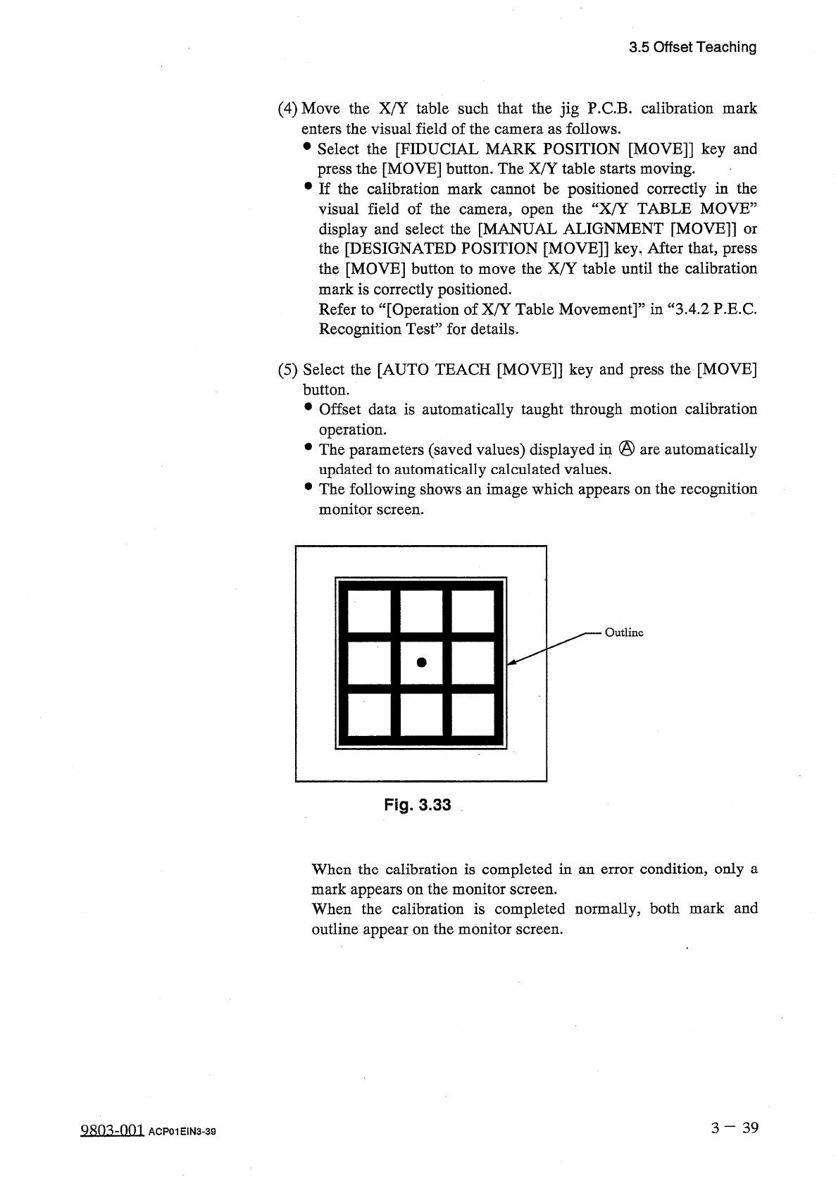
•
The
following
shows
an
image
which
appears
on
the
recognition
monitor
screen
.
Outline
Fig
.
3.33
When
the
calibration
is
completed
in
an
error
condition
,
only
a
mark
appears
on
the
monitor
screen
.
When
the
calibration
is
completed
normally
,
both
mark
and
outline
appear
on
the
monitor
screen
.
3
一
39
QRO
^
-
OOI
ACP
01
EIN
3
-
39
3.5
Offset
Teaching
(
6
)
When
teaching
operation
is
completed
with
an
abnormal
result
,
change
the
parameters
set
in
the
“
GAIN
”
and
“
LEVEL
”
text
boxes
of
the
label
“
PEC
CAMERA
”
at
the
“
CAMERA
OFFSET
”
display
.
Press
the
[
EDIT
DATA
]
key
to
open
the
“
CAMERA
OFFSET
”
display
(
Fig
,
3.33
-
1
)
.
〈
CAMERA
OFFSET
〉
PEC
CAMERA
GAIN
255
LEVEL
255
?
a
9
c
PEC
CAMERA
GAIN
:
255
4
5
6
画
TA
1
2
3
KEY
.
SET
0
±
Fig
.
3.33
-
1
Change
the
parameters
in
the
“
GAIN
”
and
“
LEVEL
”
text
boxes
of
the
label
“
PEC
CAMERA
”
and
adjust
the
contrast
and
brightness
of
the
recognition
monitor
.
Then
,
perform
the
teaching
operation
again
.
Note
:
After
teaching
is
over
,
re
-
set
“
255
”
and
“
153
”
for
the
gain
and
level
.
(
7
)
To
exit
from
the
P
.
E
.
C
.
camera
offset
teaching
session
,
select
the
[
X
/
Y
TABLE
ORIGIN
[
MOVE
]
]
key
and
press
the
[
MOVE
]
button
.
•
The
X
/
Y
table
returns
to
its
origin
.
(
8
)
Remove
the
jig
P
.
C
.
B
.
on
the
X
/
Y
table
.
3
—
4 0
QRn
^
-
nm
ACP
01
E
1
N
3
-
40
3.5
Offset
Teaching
3.5
.
5
Component
Recognition
Camera
Offset
Teaching
When
this
function
is
implemented
using
the
special
jig
nozzle
on
the
reference
head
(
No
.
5
nozzle
position
on
No
.
1
head
)
which
is
aligned
with
the
end
plane
of
the
X
/
Y
table
chute
and
moved
to
the
component
recognition
(
high
)
,
camera
#
2
magnification
(
low
)
,
rotational
offset
data
,
camera
#
2
offset
data
,
and
scope
rotation
offset
data
automatically
calculated
and
fed
back
to
each
text
box
as
component
recognition
camera
offset
data
.
position
,
camera
#
1
magnification
camera
#
1
camera
are
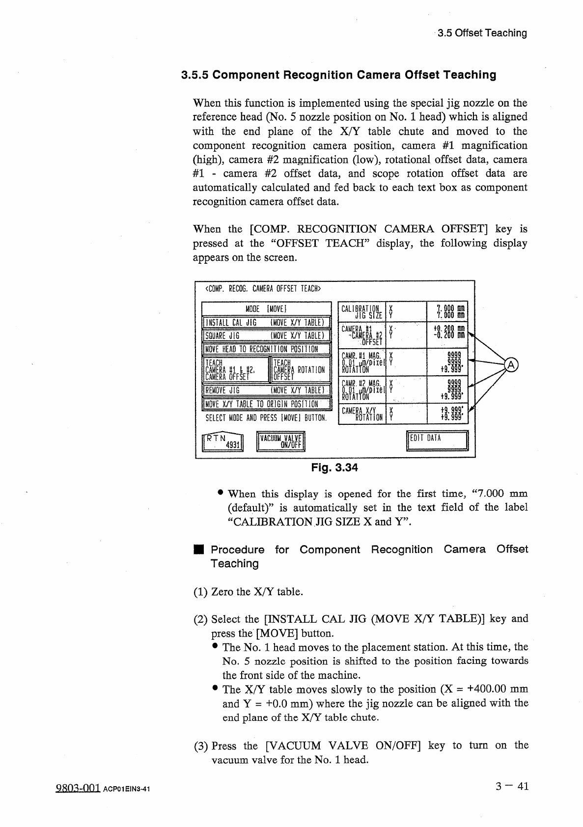
When
the
[
COMP
.
RECOGNITION
CAMERA
OFFSET
]
key
is
pressed
at
the
“
OFFSET
TEACH
”
display
,
the
following
display
appears
on
the
screen
.
<
C
0
MP
.
RECOG
.
CAMERA
OFFSET
TEACH
〉
MODE
Ei
CAU
;
鼎
X
Y
INSTALL
CAL
JIG
(
MOVE
X
/
Y
TABU
)
CA
®
L
m
x
-
m
(
MOVE
X
/
Y
TABLEf
Y
SQUARE
illG
m
MOVE
BEAD
TO
RECOGNITION
POSH
ION
9999
CAMRJ
1
MAG
翼
p
X
ixel
Y
m
TEACH
TEACH
A
鹋鼢瞧爛
Jl
恪
I
ROTATION
X
(
MOVE
X
/
Y
TABLE
)
REMOVE
JIG
MOVE
X
/
Y
TABLE
TD
ORIGIN
POSH
I
ON
隱
MON
X
SELECT
MODE
AND
PRESS
IMOVE
]
BUTTON
.
Y
EDIT
DATA
VACUyMQVALVE
Fig
.
3.34
•
When
this
display
is
opened
for
the
first
time
,
“
7.000
mm
(
default
)
”
is
automatically
set
in
the
text
field
of
the
label
CALIBRATION
JIG
SIZE
X
and
Y
”
.
u
■
Procedure
for
Component
Recognition
Camera
Offset
Teaching
(
1
)
Zero
the
X
/
Y
table
.
(
2
)
Select
the
[
INSTALL
CAL
JIG
(
MOVE
X
/
Y
TABLE
)
]
key
and
press
the
[
MOVE
]
button
.
•
The
No
.
1
head
moves
to
the
placement
station
.
At
this
time
,
the
No
.
5
nozzle
position
is
shifted
to
the
position
facing
towards
the
front
side
of
the
machine
.
•
The
X
/
Y
table
moves
slowly
to
the
position
(
X
=
+
400.00
mm
and
Y
=
十
0.0
mm
)
where
the
jig
nozzle
can
be
aligned
with
the
end
plane
of
the
X
/
Y
table
chute
.
(
3
)
Press
the
[
VACUUM
VALVE
ON
/
OFF
]
key
to
turn
on
the
vacuum
valve
for
the
No
.
1
head
.
3
—
4 1
9803
-
001
ACP
01
EIN
3
-
41